Configuration procedure – H3C Technologies H3C S10500 Series Switches User Manual
Page 225
214
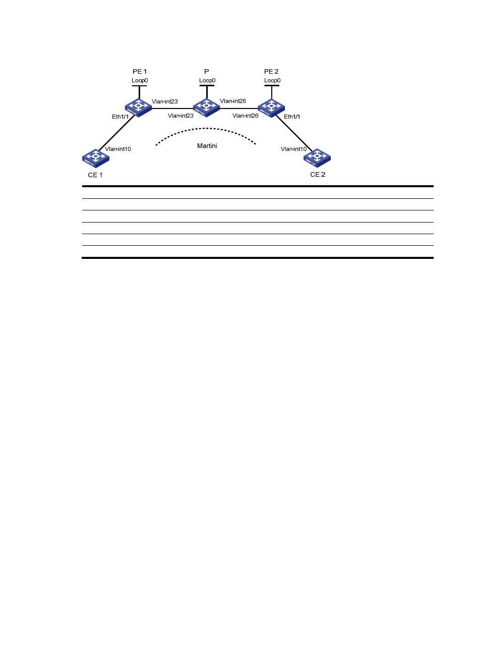
Figure 51 Network diagram for configuring MPLS L2VPN connections on service instances
Device Interface IP
address
Device Interface IP
address
CE 1
Vlan-int10
100.1.1.1/24
P
Loop0
192.4.4.4/32
PE 1
Loop0
192.2.2.2/32
Vlan-int23
23.1.1.2/24
Vlan-int23 23.1.1.1/24
Vlan-int26 26.2.2.2/24
CE 2
Vlan-int10
100.1.1.2/24
PE 2
Loop0
192.3.3.3/32
Vlan-int26
26.2.2.1/24
Configuration procedure
1.
Configure CE 1.
[Sysname] sysname CE1
[CE1] interface vlan-interface 10
[CE1-Vlan-interface10] ip address 100.1.1.1 24
2.
Configure PE 1.
[Sysname] sysname PE1
[PE1] interface loopback 0
[PE1-LoopBack0] ip address 192.2.2.2 32
[PE1-LoopBack0] quit
# Configure the LSR ID and enable MPLS globally.
[PE1] mpls lsr-id 192.2.2.2
[PE1] mpls
[PE1-mpls] quit
# Enable L2VPN and MPLS L2VPN.
[PE1] l2vpn
[PE1-l2vpn] mpls l2vpn
[PE1-l2vpn] quit
# Enable LDP globally.
[PE1] mpls ldp
[PE1-mpls-ldp] quit
# Configure PE 1 to establish an LDP remote session with PE 2.
[PE1] mpls ldp remote-peer 1
[PE1-mpls-ldp-remote-1] remote-ip 192.3.3.3
[PE1-mpls-ldp-remote-1] quit