Vpls configuration examples, Binding service instances with vpls instances, Network requirements – H3C Technologies H3C S10500 Series Switches User Manual
Page 184: Configuration procedure
173
To do…
Use the command…
Remarks
Display information about one or
all VPLS instances
display vsi [ vsi-name ] [ verbose ]
[ | { begin | exclude | include }
regular-expression ]
Available in any view
Display information about remote
VPLS connections
display vsi remote { bgp | ldp } [ |
{ begin | exclude | include }
regular-expression ]
Available in any view
Display information about one or
all PW class templates
display pw-class [ pw-class-name ]
[ | { begin | exclude | include }
regular-expression ]
Available in any view
Clear the MAC address table of
one or all VPLS instances
reset mac-address vsi [ vsi-name ]
Available in user view
VPLS configuration examples
Binding service instances with VPLS instances
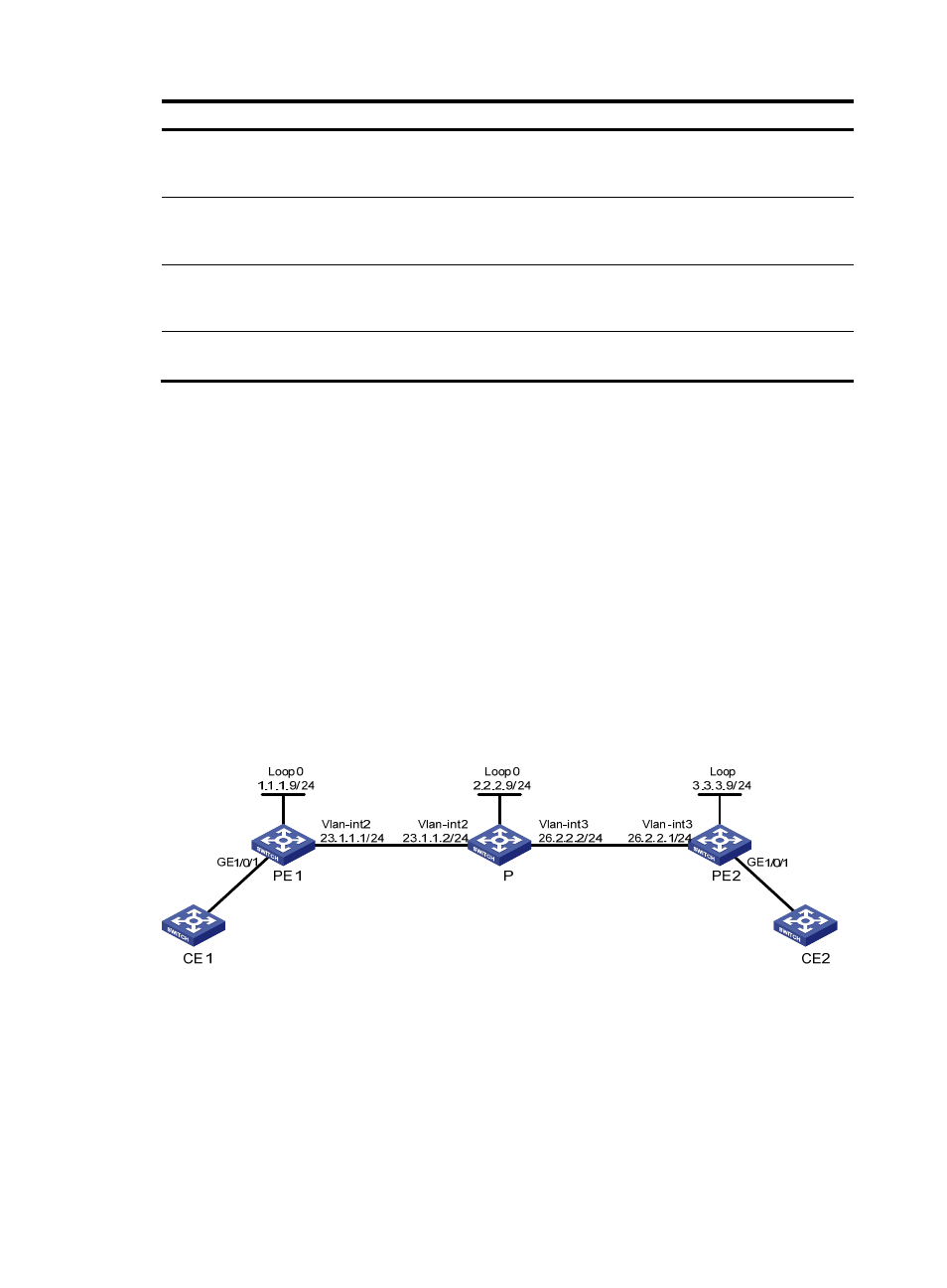
Network requirements
CE 1 and CE 2 are connected to PE 1 and PE 2 respectively through VLANs.
Configure VPLS instance aaa to use LDP (Martini mode) and VPLS instance bbb to use BGP (Kompella
mode), and configure the AS number as 100.
On PE 1 and PE 2: Configure service instance 1000 to match packets that are received on
GigabitEthernet 1/0/1 and carry the VLAN tag of 100. Bind service instance 1000 to VPLS instance
aaa. Configure service instance 2000 to match packets that are received on GigabitEthernet 1/0/1 and
carry VLAN tag of 200. Bind service instance 2000 to VPLS instance bbb.
Figure 43 Network diagram for binding service instances with VPLS instances
Configuration procedure
1.
Configure PE 1.
[Sysname] sysname PE1
[PE1] interface loopback 0
[PE1-LoopBack0] ip address 1.1.1.9 32
[PE1-LoopBack0] quit