Using tunnels to advertise vpn routes, Network requirements, Configuration considerations – H3C Technologies H3C S10500 Series Switches User Manual
Page 38
27
192.168.0.0/24 BGP 255 2 30.1.1.1 Vlan30
# Perform similar configuration on the MCE and PE 1 for VPN 2. Redistribute the OSPF routes of VPN
instance vpn2 into the eBGP routing table. (Details not shown)
The following output shows that PE 1 has learned the private route of VPN 2 through BGP:
[PE1] display ip routing-table vpn-instance vpn2
Routing Tables: vpn2
Destinations : 5 Routes : 5
Destination/Mask Proto Pre Cost NextHop Interface
40.1.1.0/24 Direct 0 0 40.1.1.2 Vlan40
40.1.1.2/32 Direct 0 0 127.0.0.1 InLoop0
127.0.0.0/8 Direct 0 0 127.0.0.1 InLoop0
127.0.0.1/32 Direct 0 0 127.0.0.1 InLoop0
192.168.10.0/24 BGP 255 2 40.1.1.1 Vlan40
Now, the MCE has redistributed the OSPF routes of the two VPN instances into the eBGP routing tables
of PE 1.
Using tunnels to advertise VPN routes
Network requirements
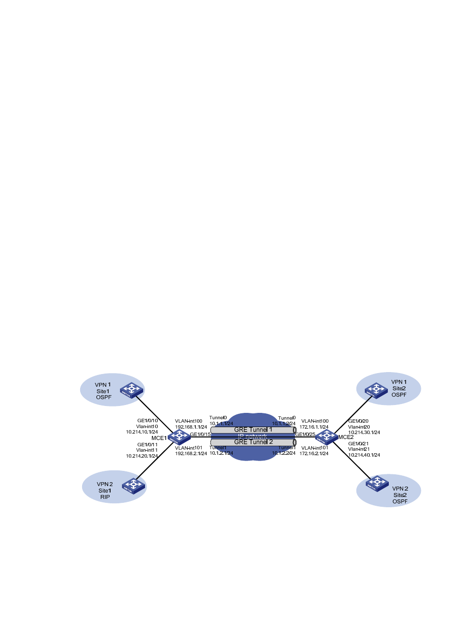
As shown in
, MCE 1 and MCE 2 communicate with each other through GRE tunnels, and both
are connected with sites of VPN 1 and VPN 2. The sites of VPN 1 use routing protocol OSPF and reside
in the backbone area, that is, area 0. The two sites of VPN 2 use RIP and OSPF, respectively, and the
OSPF area 0 is used.
Configure MCE 1 and MCE 2 to correctly advertise routing information of the two VPNs.
Figure 8 Network diagram for using MCE to advertise VPN routes through tunnels
Configuration considerations
As shown in
, because a GRE tunnel is configured for each VPN to transmit data and routing
information of the VPN, you can create a VPN instance for each VPN and bind the VPN instances to
specific interfaces (the tunnel interfaces and interfaces connected to the VPN sites). In this way the current