Example for configuring kompella mpls l2vpn, Network requirements, Configuration procedure – H3C Technologies H3C S10500 Series Switches User Manual
Page 229
218
Example for configuring Kompella MPLS L2VPN
Network requirements
CEs are connected to PEs through VLAN interfaces.
A Kompella MPLS L2VPN is established between CE 1 and CE 2.
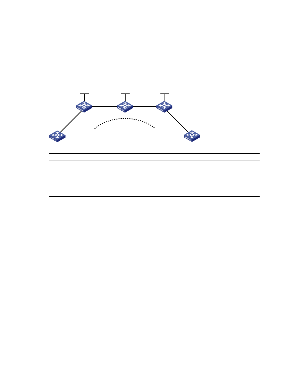
Figure 52 Network diagram for configuring Kompella MPLS L2VPN
Vlan-int20
Vlan-int20
Loop0
Vlan-int30
Vlan-int30
Vlan-int10
Vlan-int10
Vlan-int10
Vlan-int10
Loop0
Loop0
PE 1
PE 2
P
CE 1
CE 2
Kompella
Device Interface IP
address
Device Interface IP
address
CE 1
Vlan-int10
100.1.1.1/24
P
Loop0
3.3.3.3/32
PE 1
Loop0
2.2.2.2/32
Vlan-int20
10.1.1.2/24
Vlan-int20 10.1.1.1/24
Vlan-int30 10.2.2.2/24
CE 2
Vlan-int10
100.1.1.2/24
PE 2
Loop0
4.4.4.4/32
Vlan-int30
10.2.2.1/24
Configuration procedure
1.
Configure IGP on the MPLS backbone.
This example uses OSPF. (Details not shown)
After configuration, issuing the display ip routing-table command on each LSR, you will see that it has
learned the routes to the LSR IDs of the other LSRs. Issuing the display ospf peer command, you will see
that OSPF adjacencies have been established and reached the Full state.
2.
Configure basic MPLS and LDP to establish LDP LSPs.
Details not shown
After configuration, you can issue the display mpls ldp session and display mpls ldp peer commands to
view the LDP sessions and peer relationship established, or the display mpls lsp command to view the
LSPs established.
3.
Configure BGP L2VPN capability.
# Configure PE 1.
[Sysname] sysname PE1
[PE1] l2vpn
[PE1-l2vpn] mpls l2vpn
[PE1-l2vpn] quit
[PE1] bgp 100
[PE1-bgp] peer 4.4.4.4 as-number 100