Configuration procedure – H3C Technologies H3C S10500 Series Switches User Manual
Page 221
210
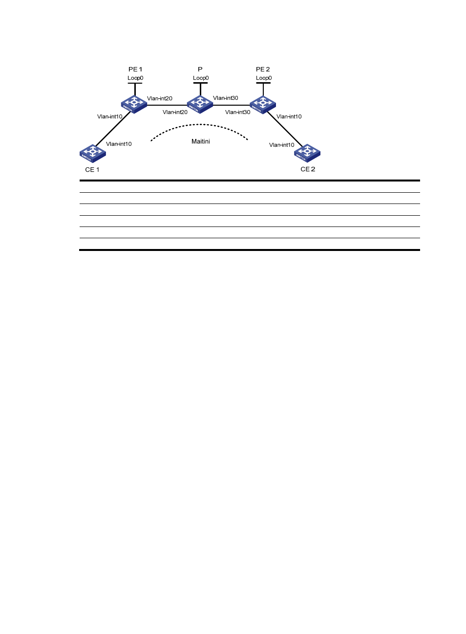
Figure 50 Network diagram for configuring Martini MPLS L2VPN
Device Interface IP
address
Device Interface IP
address
CE 1
Vlan-int10
100.1.1.1/24
P
Loop0
192.4.4.4/32
PE 1
Loop0
192.2.2.2/32
Vlan-int20
10.1.1.2/24
Vlan-int20 10.1.1.1/24
Vlan-int30 10.2.2.2/24
CE 2
Vlan-int10
100.1.1.2/24
PE 2
Loop0
192.3.3.3/32
Vlan-int30
10.2.2.1/24
Configuration procedure
1.
Configure CE 1.
[Sysname] sysname CE1
[CE1] interface vlan-interface 10
[CE1-Vlan-interface10] ip address 100.1.1.1 24
2.
Configure PE 1.
# Configure the LSR ID and enable MPLS globally.
[Sysname] sysname PE1
[PE1] interface loopback 0
[PE1-LoopBack0] ip address 192.2.2.2 32
[PE1-LoopBack0] quit
[PE1] mpls lsr-id 192.2.2.2
[PE1] mpls
# Enable L2VPN and MPLS L2VPN.
[PE1] l2vpn
[PE1-l2vpn] mpls l2vpn
[PE1-l2vpn] quit
# Enable LDP globally.
[PE1] mpls ldp
[PE1-mpls-ldp] quit
# Establish a remote session between PE 1 and PE 2.
[PE1] mpls ldp remote-peer 1
[PE1-mpls-ldp-remote-1] remote-ip 192.3.3.3
[PE1-mpls-ldp-remote-1] quit
# Configure the interface connected with the P device, and enable LDP on the interface.