How mce works, Using mce in tunneling applications – H3C Technologies H3C S10500 Series Switches User Manual
Page 16
5
How MCE works
shows how an MCE maintains the routing entries of multiple VPNs and how an MCE exchanges
VPN routes with PEs.
Figure 3 Network diagram for the MCE function
PE1
PE
PE2
P
P
VPN 2
Site 2
VPN 1
Site 1
MCE
VLAN-int2
VLAN-int3
CE
Site 1
VPN 2
CE
VPN 1
Site 2
VLAN-int7
VLAN-int8
On the left-side network, there are two VPN sites, both of which are connected to the MPLS backbone
through the MCE device. VPN 1 and VPN 2 on the left-side network must establish a tunnel with VPN 1
and VPN 2 on the right-side network, respectively.
With MCE enabled, routing tables can be created for VPN 1 and VPN 2 individually, VLAN-interface 2
can be bound to VPN 1, and VLAN-interface 3 can be bound to VPN 2. When receiving a piece of
routing information, MCE determines the source of the routing information according to the number of
the interface receiving the information. It then maintains the corresponding routing table accordingly.
You must also bind the interfaces to the VPNs on PE 1 in the same way as those on the MCE device. The
MCE device is connected to PE 1 through a trunk, which permits packets of VLAN 2 and VLAN 3 with
VLAN tags carried. In this way, PE 1 can determine the VPN a received packet belongs to according to
the VLAN tag of the packet and passes the packet to the corresponding tunnel.
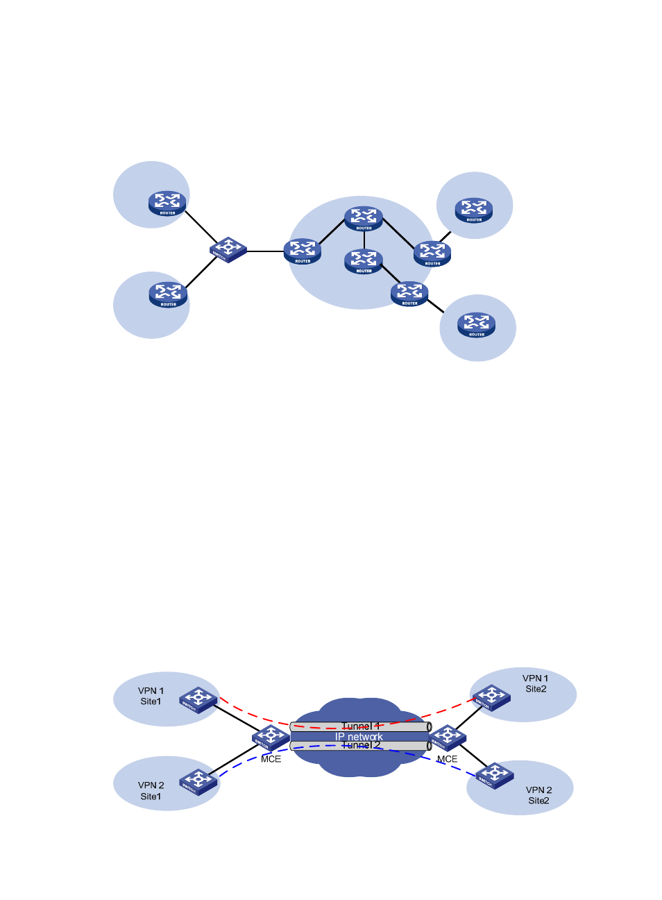
Using MCE in tunneling applications
In addition to MPLS L3VPN, tunneling technologies can also be used to implement other types of VPNs.
The MCE function provided by the switch can be applied in VPN applications based on tunneling.
Figure 4 Network diagram for using MCE in a tunneling application (1)