Mpls te in mpls l3vpn configuration example, Network requirements, Configuration procedure – H3C Technologies H3C S10500 Series Switches User Manual
Page 162

151
[SwitchB] mpls
[SwitchB-mpls] mpls te timer fast-reroute 5
[SwitchB-mpls] quit
# Bring the protected outgoing interface up on PLR.
[SwitchB] interface vlan-interface 2
[SwitchB-Vlan-interface2] undo shutdown
%Sep 7 09:01:31 2004 SwitchB IFNET/5/UPDOWN:Line protocol on the interface Vlan-interface2
turns into UP state
Perform the display interface tunnel 4 command on Switch A to identify the state of the primary LSP. You
can see that the tunnel interface is up.
About five seconds later, perform the display mpls lsp verbose command on Switch B. You can see that
Tunnel5 is still bound with interface VLAN-interface 2 and is unused.
7.
Create a static route for routing MPLS TE tunnel traffic
[SwitchA] ip route-static 4.1.1.2 24 tunnel 4 preference 1
Perform the display ip routing-table command on Switch A. You can see a static route entry with Tunnel4
as the outgoing interface.
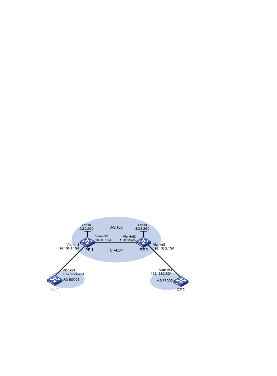
MPLS TE in MPLS L3VPN configuration example
Network requirements
CE 1 and CE 2 belong to VPN 1. They are connected to the MPLS backbone respectively through PE 1
and PE 2. The IGP protocol running on the MPLS backbone is OSPF.
•
Set up an MPLS TE tunnel to forward traffic of VPN 1 from PE 1 to PE 2.
•
To allow the MPLS L3VPN traffic to travel the TE tunnel, configure a tunneling policy to use a CR-LSP
as the VPN tunnel when creating the VPN.
Figure 37 MPLS TE application in VPN (on switches)
Configuration procedure
1.
Configure OSPF, ensuring that PE 1 and PE 2 can learn LSR-ID routes from each other.
# Configure PE 1.
[PE1] interface loopback 0
[PE1-LoopBack0] ip address 2.2.2.2 255.255.255.255
