Example for configuring svc mpls l2vpn, Network requirements, Configuration procedure – H3C Technologies H3C S10500 Series Switches User Manual
Page 217
206
Example for configuring SVC MPLS L2VPN
Network requirements
CEs are connected to PEs through VLAN interfaces.
An SVC MPLS L2VPN is established between CE 1 and CE 2.
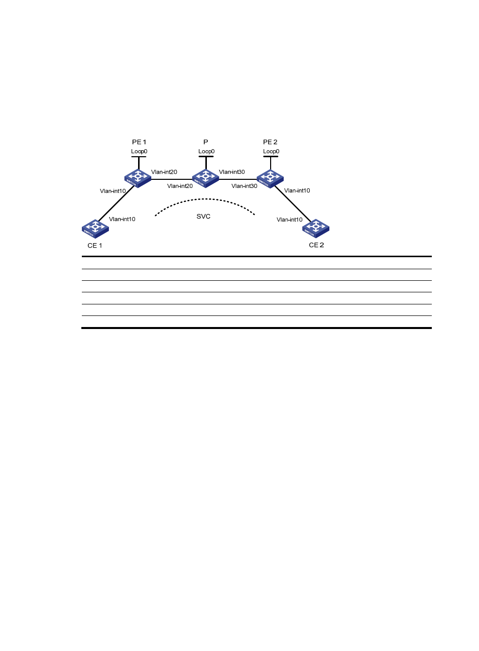
Figure 49 Network diagram for configuring SVC MPLS L2VPN
Device Interface IP
address
Device Interface IP
address
CE 1
Vlan-int10
100.1.1.1/24
P
Loop0
192.4.4.4/32
PE 1
Loop0
192.2.2.2/32
Vlan-int30
10.2.2.2/24
Vlan-int20 10.1.1.1/24
Vlan-int20 10.1.1.2/24
CE 2
Vlan-int10
100.1.1.2/24
PE 2
Loop0
192.3.3.3/32
Vlan-int30
10.2.2.1/24
Configuration procedure
The following are the main steps to the configuration:
•
Configure MPLS basic forwarding capability on the PEs and P device. This includes configuring the
LSR ID, enabling MPLS and LDP, and running IGP (OSPF in this example) between PE 1, the P device,
and PE 2 to establish LSPs.
•
Establish an SVC MPLS L2VPN connection. This includes enabling MPLS L2VPN on PE 1 and PE 2
and establishing an SVC connection and specifying the VC labels.
The following is the detailed configuration procedure:
1.
Configure CE 1.
[Sysname] sysname CE1
[CE1] interface vlan-interface 10
[CE1-Vlan-interface10] ip address 100.1.1.1 24
2.
Configure PE 1.
# Configure the LSR ID and enable MPLS globally.
[Sysname] sysname PE1
[PE1] interface loopback 0
[PE1-LoopBack0] ip address 192.2.2.2 32
[PE1-LoopBack0] quit
[PE1] mpls lsr-id 192.2.2.2