Configuring a backup link for h-vpls access, Network requirements, Configuration procedure – H3C Technologies H3C S10500 Series Switches User Manual
Page 189
178
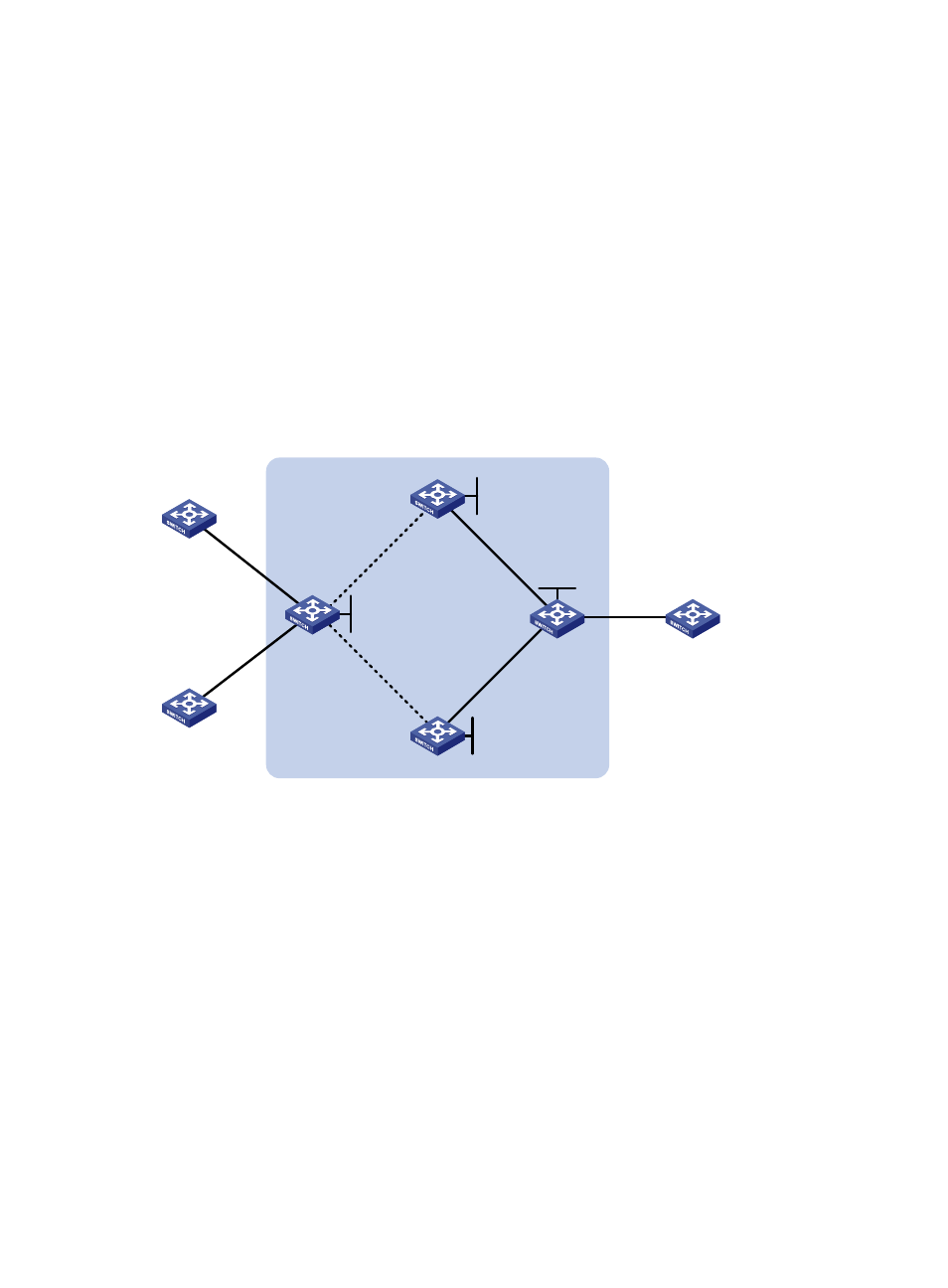
Configuring a backup link for H-VPLS access
Network requirements
CE 1 and CE 2 are connected to UPE through VLANs.
UPE establishes a PW connection (U-PW) with NPE 1 and NPE 2, respectively, with the NPE 2 link as the
backup.
NPE 1 and NPE 2 each establish a PW connection (N-PW) with NPE 3. CE 3 is connected to the network
through NPE 3.
UPE is connected to NPE 1 through VLAN-interface 12 and to NPE 2 through VLAN-interface 13.
NPE 1 is connected to NPE 3 through VLAN-interface 15. NPE 2 is connected to NPE 3 through
VLAN-interface 16.
Configure the VPLS instance to support H-VPLS.
Figure 44 Network diagram for configuring H-VPLS backup link
CE 3
NPE 3
NPE 1
CE 1
CE 2
NPE 2
UPE
GE1/0/1
VLAN 11
GE1/0/2
VLAN 10
Vlan-int12
12.1.1.1/24
Vlan-int13
13.1.1.1/24
Vlan-int16
16.1.1.1/24
Vlan-int15
15.1.1.1/24
GE1/0/1
VLAN 10
Loo
p0
2.2.2.2/32
Loo
p0
3
.3.3.3/32
Loop0
4.4.4.4/32
Vlan-int16
16.1.1.2/24
Vlan-int15
15.1.1.2/24
Vlan-int13
13.1.1.2/24
Vlan-int12
12.1.1.2/24
Loop0
1.1.1.1/32
Configuration procedure
1.
Configure the IGP protocol on the MPLS backbone, which is OSPF in this example. (Details not
shown)
2.
Configure UPE.
# Configure basic MPLS.
[Sysname] sysname UPE
[UPE] interface loopback 0
[UPE-LoopBack0] ip address 1.1.1.1 32
[UPE-LoopBack0] quit
[UPE] mpls lsr-id 1.1.1.1
[UPE] mpls
[UPE-mpls] quit
[UPE] mpls ldp
[UPE-mpls-ldp] quit