Configuring a hub-spoke network, Network requirements, Configuration procedure – H3C Technologies H3C S10500 Series Switches User Manual
Page 293
282
Request time out
Request time out
--- 7.7.7.9 ping statistics ---
5 packet(s) transmitted
0 packet(s) received
100.00% packet loss
Configuring a hub-spoke network
Network requirements
•
The spoke-CEs are not permitted to communicate with each other directly. Data transmission
between them depends on the hub-CE.
•
Configure eBGP to exchange VPN routing information between spoke-CE and spoke-PE, and
between hub-CE and hub-PE.
•
Configure OSPF between spoke-PE and hub-PE to ensure IP connectivity between PEs, and
configure MP-iBGP to exchange VPN routing information.
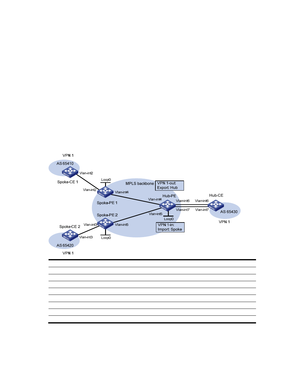
Figure 73 Network diagram for hub-spoke MPLS L3VPN
Device Interface IP
address
Device Interface IP
address
Spoke-CE
1
Vlan-int2 10.1.1.1/24
Hub-CE Vlan-int6 10.3.1.1/24
Spoke-PE 1
Loop0
1.1.1.9/32
Vlan-int7
10.4.1.1/24
Vlan-int2
10.1.1.2/24
Hub-PE
Loop0
2.2.2.9/32
Vlan-int4 172.1.1.1/24
Vlan-int4 172.1.1.2/24
Spoke-CE
2
Vlan-int3 10.2.1.1/24
Vlan-int5 172.2.1.2/24
Spoke-PE 2
Loop0
3.3.3.9/32
Vlan-int6
10.3.1.2/24
Vlan-int3 10.2.1.2/24
Vlan-int7 10.4.1.2/24
Vlan-int5
172.2.1.1/24
Configuration procedure
1.
Configure an IGP in the MPLS backbone to ensure IP connectivity between spoke-PE and hub-PE.
# Configure Spoke-PE 1.