Configuration procedure – H3C Technologies H3C S10500 Series Switches User Manual
Page 342
331
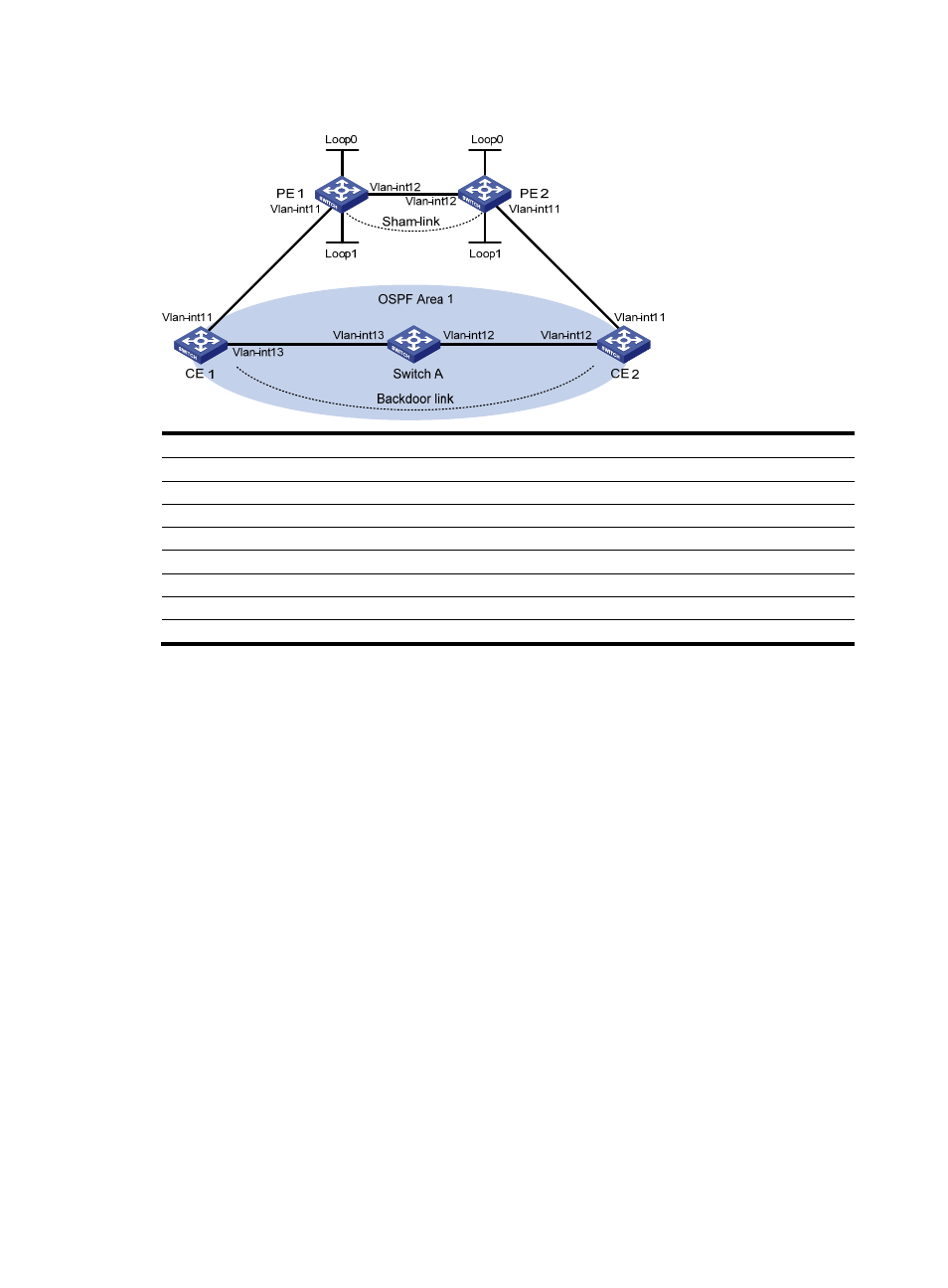
Figure 80 Configure an OSPF sham link
Device Interface IP
address
Device Interface IP
address
CE 1
Vlan-int11
100.1.1.1/24
CE 2
Vlan-int11
120.1.1.1/24
Vlan-int13 20.1.1.1/24
Vlan-int12 30.1.1.2/24
PE 1
Loop0
1.1.1.9/32
PE 2
Loop0
2.2.2.9/32
Loop1 3.3.3.3/32
Loop1 5.5.5.5/32
Vlan-int11 100.1.1.2/24
Vlan-int11 120.1.1.2/24
Vlan-int12 10.1.1.1/24
Vlan-int12 10.1.1.2/24
Switch
A
Vlan-int11
20.1.1.2/24
Vlan-int12
30.1.1.1/24
Configuration procedure
1.
Configure OSPF on the customer networks
Configure conventional OSPF on CE 1, Switch A, and CE 2 to advertise segment addresses of the
interfaces as shown in
. (Details not shown)
After completing the configurations, CE 1 and CE 2 can learn the OSPF route to the VLAN interface 1
of each other. The following takes CE 1 as an example:
Routing Tables: Public
Destinations : 9 Routes : 9
Destination/Mask Proto Pre Cost NextHop Interface
20.1.1.0/24 Direct 0 0 20.1.1.1 Vlan13
20.1.1.1/32 Direct 0 0 127.0.0.1 InLoop0
20.1.1.2/32 Direct 0 0 20.1.1.2 Vlan13
30.1.1.0/24 OSPF 10 3124 20.1.1.2 Vlan13
100.1.1.0/24 Direct 0 0 100.1.1.1 Vlan11
100.1.1.1/32 Direct 0 0 127.0.0.1 InLoop0
120.1.1.0/24 OSPF 10 3125 20.1.1.2 Vlan13
127.0.0.0/8 Direct 0 0 127.0.0.1 InLoop0
127.0.0.1/32 Direct 0 0 127.0.0.1 InLoop0
2.
Configure MPLS L3VPN on the backbone
# Configure MPLS basic capability and MPLS LDP on PE 1 to establish LDP LSPs.