Network requirements, Configuration procedure – H3C Technologies H3C S10500 Series Switches User Manual
Page 148
137
Graceful Restart State: Ready
Restart Time: 120 Sec Recovery Time: 300 Sec
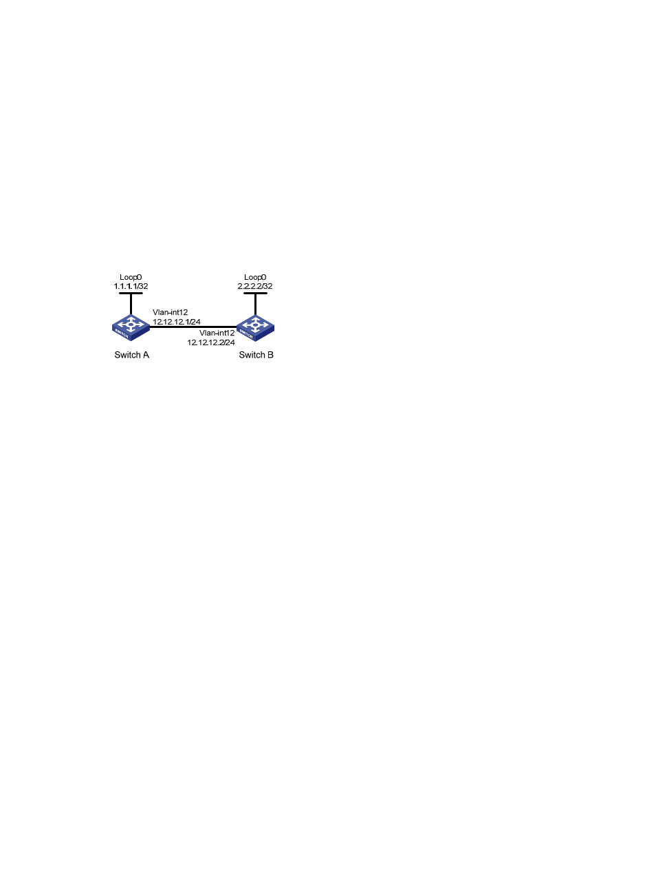
MPLS RSVP-TE and BFD cooperation configuration example
Network requirements
•
Switch A and Switch B are connected directly. Enable MPLS RSVP-TE BFD on the VLAN interfaces
connecting the two switches, and run OSPF on the switches to ensure reachability at the network
layer.
•
If the link between Switch A and Switch B fails, BFD can detect the failure quickly and inform MPLS
RSVP-TE of the failure.
Figure 34 Network diagram for MPLS RSVP-TE and BFD cooperation configuration
Configuration procedure
1.
Configure basic MPLS RSVP-TE
# Configure Switch A.
[SwitchA] mpls lsr-id 1.1.1.1
[SwitchA] mpls
[SwitchA-mpls] mpls te
[SwitchA-mpls] mpls rsvp-te
[SwitchA-mpls] quit
[SwitchA] interface vlan-interface 12
[SwitchA-Vlan-interface12] mpls
[SwitchA-Vlan-interface12] mpls te
[SwitchA-Vlan-interface12] mpls rsvp-te
[SwitchA-Vlan-interface12] mpls rsvp-te bfd enable
[SwitchA-Vlan-interface12] quit
# Configure Switch B.
[SwitchB] mpls lsr-id 2.2.2.2
[SwitchB] mpls
[SwitchB-mpls] mpls te
[SwitchB-mpls] mpls rsvp-te
[SwitchB-mpls] quit
[SwitchB] interface vlan-interface 12
[SwitchB-Vlan-interface12] mpls
[SwitchB-Vlan-interface12] mpls te
[SwitchB-Vlan-interface12] mpls rsvp-te
[SwitchB-Vlan-interface12] mpls rsvp-te bfd enable