Figure 6-10, Block diagram of a blower, Configuring and operating the system – Artesyn Centellis 4100 Installation and Use (2015) User Manual
Page 191
Configuring and Operating the System
Centellis 4100 Installation and Use (6806800D82E)
193
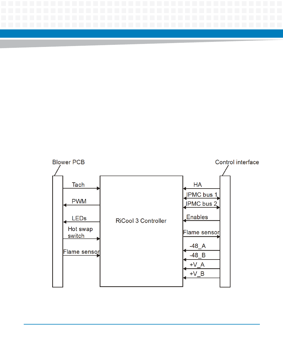
Each of the blower tray units contains an IPMC which is located on both IPMB-A and IPMB-B
buses. Individual blower failures are detected by monitoring the blower rotation speed.
Rotation which is 15% below demand is deemed to be a blower failure. Usually, the cooling
system runs the blowers at speed levels between 15% and 75%, depending on ambient
temperature and system configuration. In case of a single blower failure the blowers run at
100% to still provide full air pressure within the area between blowers and boards/blades.
Each blower tray monitors and reports air temperature and failure conditions to the shelf
manager. The shelf manager controls the blower speed based on sensor and failure information
acquired from blower and board sensors. If a blower tray looses IPMI communication to the
shelf manager, it automatically runs its blower motor at full speed.
The following figure shows the block diagram with the main components of the blower:
Figure 6-10 Block Diagram of a Blower
- AXP640 Installation and Use (April 2015) AXP1620 Installation and Use (August 2014) AXP1620 Installation and Use (September 2014) Centellis-4440/AXP-1440 Installation and Use (August 2014) Centellis-4440/AXP-1440 Installation and Use (July 2014) AXP1620 Installation and Use (May 2014) Centellis-4440/AXP1440 Installation and Use (August 2014) Centellis-4440/AXP-1440 Installation and Use (May 2014) Centellis-4440/AXP1440 Installation and Use (September 2014) AXP640 Installation and Use (May 2014)