Figure 6-7, Functional block diagram of a pem, Configuring and operating the system – Artesyn Centellis 4100 Installation and Use (2015) User Manual
Page 185
Configuring and Operating the System
Centellis 4100 Installation and Use (6806800D82E)
187
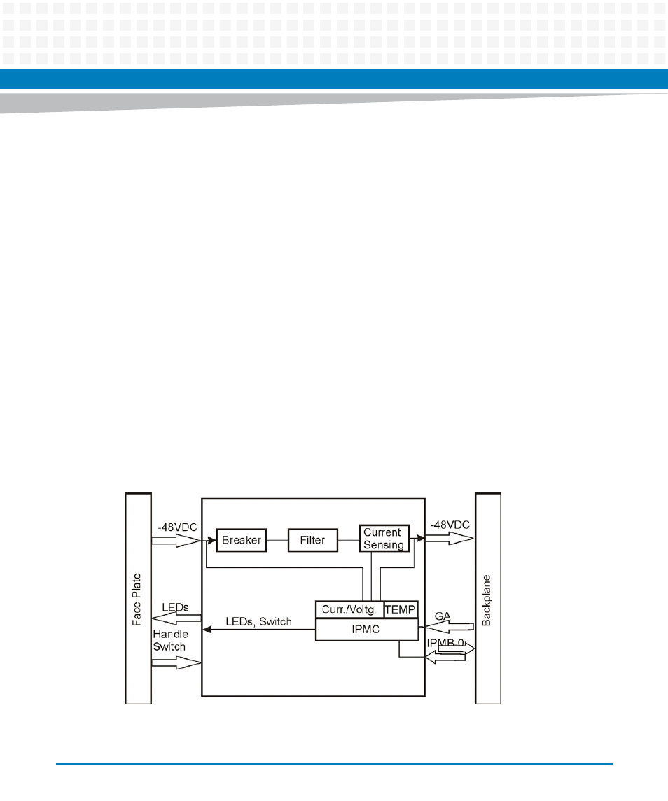
Provision of monitoring information to the shelf manager
For a description of the sensors refer to the PEM and Blowers of Centellis 4100: Control via
IPMI Programmer’s Reference.
Power feed voltage and current measurement
Temperature sensing
Power filtering
Input power monitoring within the power distribution path by the IPMC
The IPMC is located on both IPMB-A and IPMB-B buses.
Each PEM is connected via a Positronic PLC series 3x6 connector and a 3x10 connector. The DIN
connector has multiple levels of mating to allow hot insertion and removal. The I/O panel
comprises a power feed input and a hot swap handle switch, hot swap and status LEDs.
All PEMs are single width modules with dual M6 insulated studs and power filtering. The system
includes a full IPM interface for 50A.
The PEM supports the complete functionality as defined by the PICMG 3.0 specification.
The following figure illustrates the function blocks of the PEM.
Figure 6-7
Functional Block Diagram of a PEM
- AXP640 Installation and Use (April 2015) AXP1620 Installation and Use (August 2014) AXP1620 Installation and Use (September 2014) Centellis-4440/AXP-1440 Installation and Use (August 2014) Centellis-4440/AXP-1440 Installation and Use (July 2014) AXP1620 Installation and Use (May 2014) Centellis-4440/AXP1440 Installation and Use (August 2014) Centellis-4440/AXP-1440 Installation and Use (May 2014) Centellis-4440/AXP1440 Installation and Use (September 2014) AXP640 Installation and Use (May 2014)