Fru installation – Artesyn Centellis 4100 Installation and Use (2015) User Manual
Page 116
FRU Installation
Centellis 4100 Installation and Use (6806800D82E)
118
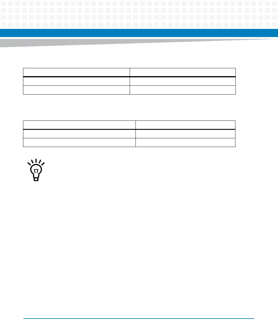
Jumpers 2, 3, 6, and 9 determine the voltage to be detected by the relays.
Jumpers 4, 5, 7, and 8 define if the input signal is active high or active low. It is recommended
to leave them at the default position 1-2.
4.2.4.1.2 Rotary Switch Settings
The two rotary switches on the alarm board are used to set the SGA. The first byte of the shelf
address of the shelf FRU information will automatically be set to the SGA value.
Metal Pins
Voltage
1 and 2 (default)
40 - 72V
2 and 3
5 - 12V
Metal Pins
Signal
1 and 2 (default)
Active high
2 and 3
Active low
Both jumpers (4 and 5 or 7 and 8) must always be in the same position in order for the input
to function properly.
This manual is related to the following products:
- AXP640 Installation and Use (April 2015) AXP1620 Installation and Use (August 2014) AXP1620 Installation and Use (September 2014) Centellis-4440/AXP-1440 Installation and Use (August 2014) Centellis-4440/AXP-1440 Installation and Use (July 2014) AXP1620 Installation and Use (May 2014) Centellis-4440/AXP1440 Installation and Use (August 2014) Centellis-4440/AXP-1440 Installation and Use (May 2014) Centellis-4440/AXP1440 Installation and Use (September 2014) AXP640 Installation and Use (May 2014)