5 power subsystem, 1 power supply, Figure 6-6 – Artesyn Centellis 4100 Installation and Use (2015) User Manual
Page 184: Power entry modules location, Figure "power, Power subsystem
Configuring and Operating the System
Centellis 4100 Installation and Use (6806800D82E)
186
6.5
Power Subsystem
In this section you can find information on the power supplies, the power distribution, as well
as the PEM specifications.
6.5.1
Power Supply
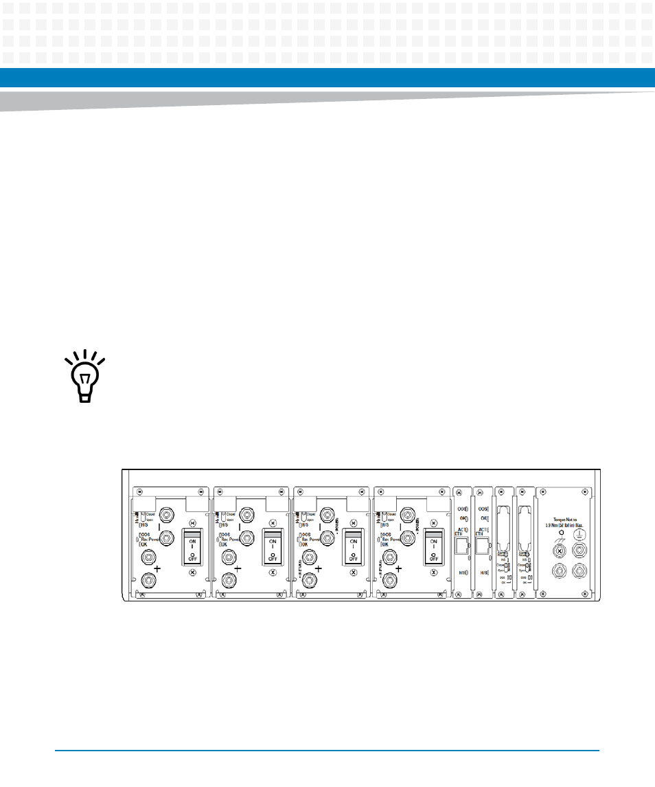
Four field-maintainable intelligent PEMs are installed beneath the rear slots of the backplane.
The PEMs A1 and B1 supply the odd numbered slots, the blowers and shelf manager boards,
the PEMs A2 and B2 the even numbered slots.
At the minimum operating voltage (40V), this power entry supports 4000W.
Important features of the PEMs are:
Redundancy such that a single PEM failure will still provide full power to the system
Hot-swap
At a minimum, one of PEMs A1 or B1, and one of PEMS A2 or B2 must be connected in order to
have sufficient power for the blades.
Figure 6-6
Power Entry Modules Location
- AXP640 Installation and Use (April 2015) AXP1620 Installation and Use (August 2014) AXP1620 Installation and Use (September 2014) Centellis-4440/AXP-1440 Installation and Use (August 2014) Centellis-4440/AXP-1440 Installation and Use (July 2014) AXP1620 Installation and Use (May 2014) Centellis-4440/AXP1440 Installation and Use (August 2014) Centellis-4440/AXP-1440 Installation and Use (May 2014) Centellis-4440/AXP1440 Installation and Use (September 2014) AXP640 Installation and Use (May 2014)