Rockwell Automation 20D PowerFlex 700H and 700S Frame 9-14 Drives Installation - A4 Size User Manual
Page 155
Frame 14 Installation
11-9
Ungrounded, High Resistive
Ground or Grounded B
Phase Delta Installations
Frame 14 size drives are equipped with common mode capacitors. To guard
against drive damage, these capacitors should be disconnected depending
upon the type of ground system on which the drive is installed.
To access and move the common mode jumper(s) and disconnect the
capacitor connections you must first move the Control frame and remove
the protective covers from the Converter unit. These steps are detailed on
the following pages.
Note:
Refer to Wiring and Grounding Guidelines for Pulse Width
Modulated (PWM) AC Drives - Installation Instructions,
publication DRIVES-IN001…, for additional information on an
ungrounded distribution system or high resistive ground
installation.
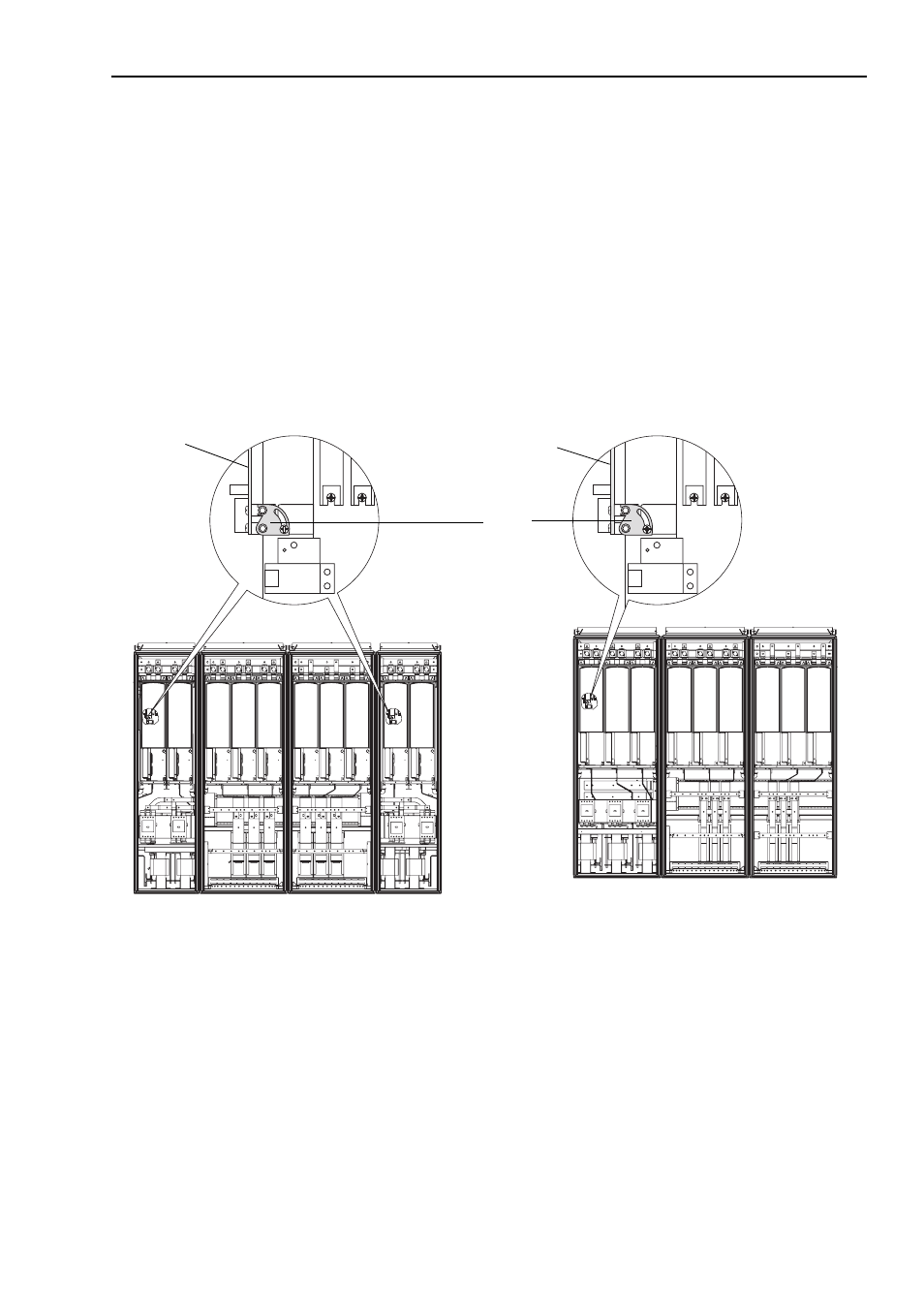
Figure 11.7 Common Mode Jumper and Rectifier Circuit Board Location
Converter
Unit
Common
Mode
Jumper
Control Frame not shown for clarity only
Inverter
Unit
Inverter
Unit
1500A Drives
Drives Above 1500A
Inverter
Unit
Converter
Unit
Inverter
Unit
Converter
Unit
There is one jumper
for each Rectifying
Module. The
Rectifying Modules
and jumpers are
located on the left
side of the power
stack on the drive’s
converter units.
Rectifier
board
Rectifier
board