Rockwell Automation 20D PowerFlex 700H and 700S Frame 9-14 Drives Installation - A4 Size User Manual
Page 47
Control Wiring for PowerFlex 700S Drives with Phase I Control
3-9
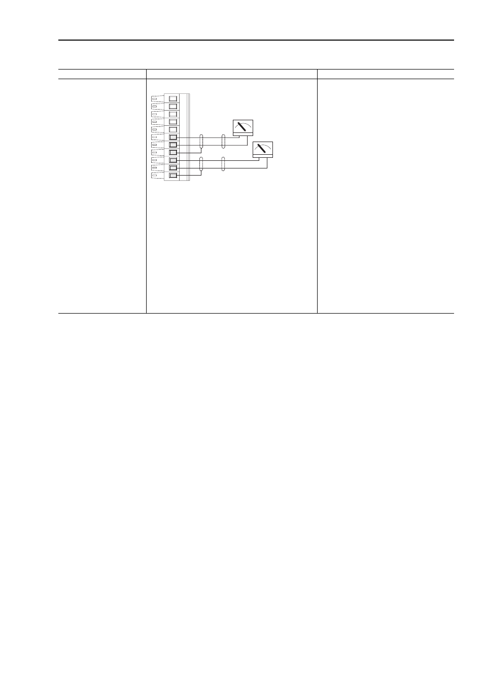
Analog Outputs
+/-10V dc or +/-1.0V dc
Used to drive analog meters
displaying speed and current
Analog Outputs Indicating Motor Speed and Motor Current
Example: Using Analog Output 1, -10V to +10V
to meter Motor RPM and direction:
•
Adjust Parameter 812 [Anlg Out1 Offset] so that
minimum speed creates a minimum signal (if
the minimum speed is zero and the minimum
signal is zero, enter a zero)
•
Adjust Parameter 817 [Anlg Out1 Scale] so that
the maximum speed creates a maximum signal
(if the maximum speed is 100% of motor base
speed and the maximum signal is 10V dc, enter
a value of 0.1)
•
Send the data to the Analog Output: Par 815
[Anlg Out1 Real] (the destination) linked to Par
300 [Motor Spd Fdbk] (the source)
Example: Using Analog Output 2, -10V to +10V
to meter Motor Current
•
Adjust Parameter 813 [Anlg Out2 Offset] so that
minimum current creates a minimum signal (if
the minimum current is zero and the minimum
signal is zero, enter a zero)
•
Adjust Parameter 822 [Anlg Out2 Scale] so that
the maximum current creates a maximum signal
(if the maximum current is 200% of motor NP
FLA and the maximum signal is 10V dc, enter a
value of 2.0)
•
Send the data to the Analog Output
Par 820 [Anlg Out2 Real] (the destination)
linked to Par 308 [Output Current] (the source)
•
Scale the Output to the source parameter
Par 822 [Anlg Out2 Scale] = xx (Par2 [Motor NP
FLA]/10V Output)
Figure 3.2 TB1 - Row B (Bottom) Wiring Examples
Input/Output
Connection Example
Required Parameter Changes
+
-
+
-
2
3
4
5
6
1
Output #1
Motor Speed
Output #2
Motor Current