Dip switch settings, Dip switch settings -11 – Rockwell Automation 20D PowerFlex 700H and 700S Frame 9-14 Drives Installation - A4 Size User Manual
Page 69
Control Wiring for PowerFlex 700S Drives with Phase II Control
4-11
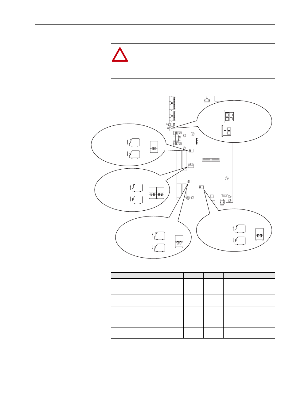
DIP Switch Settings
Figure 3 Main Control Board Dip Switches
Table E Switch Settings
!
ATTENTION: The DIP switches for Digital Inputs 4 - 6 are set
to 24V DC at the factory. If you are running a 115V AC input
application, the switches must be set as indicated below before
applying power to the drive or damage to the Main Control board
may occur.
S1
1 2
FRONT
TOP VIEW
SIDE VIEW
Up = Open = Off
Down = Closed = On
SWITCH S5
FRONT
TOP VIEW
SIDE VIEW
Up = Open = Off
Down = Closed = On
SWITCH S2
1 2
3 4
1 2
FRONT
TOP VIEW
SIDE VIEW
Up = Open = Off
Down = Closed = On
SWITCH S3
1 2
FRONT
TOP VIEW
SIDE VIEW
Up = Open = Off
Down = Closed = On
SWITCH S4
= HW Enable
= No HW Enable
JUMPER P22
1
2
3
4
1
2
3
4
Function
Default
Switch
Open
Closed
Notes
Configuring Digital
Input 6 for Hardware
Enable (HW Enbl)
pin 2-4
HW Enbl
P22
Jumper
pin 2-4
HW Enbl
pin 1-3
No Enbl
No Jmpr = HW Enbl
Analog Input 1
Voltage
S5-2
Voltage
Current
Change with Power Off
Analog Input 2
Voltage
S5-1
Voltage
Current
Change with Power Off
Digital Inputs 4-6
Voltage
24V DC
S4-1,
S4-2
115V AC
24V DC
Change with Power Off
Digital Input 1
Voltage
24V DC
S3-1
24V DC
12V DC
Change with Power Off
Digital Input 2
Voltage
24V DC
S3-2
24V DC
12V DC
Change with Power Off