Removing the protective covers, 18 frame 14 installation – Rockwell Automation 20D PowerFlex 700H and 700S Frame 9-14 Drives Installation - A4 Size User Manual
Page 164
11-18
Frame 14 Installation
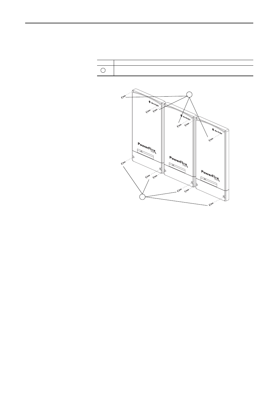
Removing the Protective Covers
You must remove the protective covers from the Inverter units in order to
gain access to the power terminals.
400 and 690 Volt Class AC Input Wiring for Frame 14 Drives
Frame 14 size drives utilize three parallel converter units or two pairs of two
parallel converter units that are pre-connected to line reactors and are fed
through motor operated circuit breakers.
Important: Parallel wiring must have the same cable dimensions, type and
routing. Non-symmetrical wiring may cause unequal loading
between the converters and reduce the drive’s ability to deliver
current to the motor.
Frame 14 drives can be ordered with or without du/dt filters. The du/dt filter
limits the rate of change of output voltage and the rate of change in the
IGBT or output transistor switching event.
Refer to the Wiring and Grounding Guidelines for Pulse Width Modulated
(PWM) AC Drives, publication DRIVES-IN001…, for minimum
inductance on installations where du/dt filters are not installed.
Task
Description
Remove the four M5 POZIDRIV screws that secure each of the three main and bottom
protective covers to the drive, then remove the protective covers.
A
DC B
US CONDU
CT
ORS AND CAP
ACIT
ORS
OPERA
TE A
T HIGH
VO
LTA
GE.
REMO
VE PO
WER
AND W
AIT 5 MINUTES BEFORE
SER
VICING
DA
NGER
!
DC B
US CONDUC
TO
RS AND CAP
ACIT
ORS
OPERA
TE A
T HIGH
VO
LTA
GE.
REMO
VE PO
WER
AND W
AIT 5 MINUTES BEFORE
SER
VICING
DA
NGER
!
DC B
US CONDUC
TO
RS AND CAP
ACIT
ORS
OPERA
TE A
T HIGH
VO
LTA
GE.
REMO
VE PO
WER
AND
WA
IT 5 MINUTES BEFORE
SER
VICING
DANGER
!
A
A