Rockwell Automation 20D PowerFlex 700H and 700S Frame 9-14 Drives Installation - A4 Size User Manual
Page 43
Control Wiring for PowerFlex 700S Drives with Phase I Control
3-5
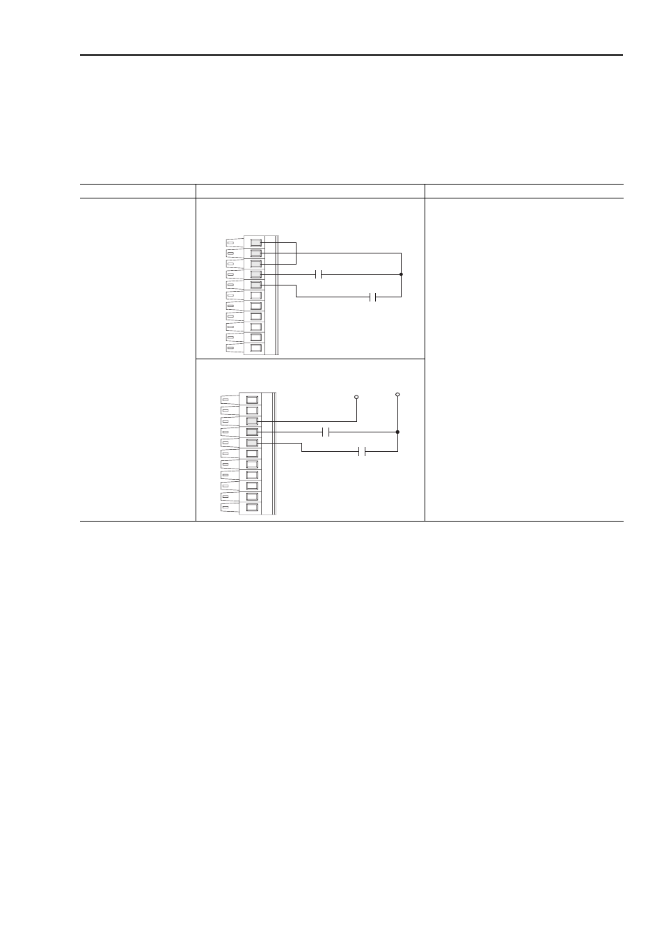
Figure 3.1 TB1 - Row T (Top) Wiring Examples
The following definitions are used throughout this section:
Source
A. Apply positive voltage through the device to the input or output.
B. Connect the input or output common (return) directly to the power supply common.
Sinking
A. Apply the positive voltage directly to the input or output common (return).
B. Connect the input or output to the power supply common through the device
Input/Output
Connection Example
Required Parameter Changes
Digital Inputs used for enable
and precharge control.
Note:
24V dc Supply - supports
only on-board digital inputs.
Do not use for circuits outside
the drive.
Sourcing Precharge and Enable Inputs - using internal power
supply
Enable - In a sourcing configuration, this circuit must
connect to a 24V dc power for the drive to run.
Precharge
Precharge control is used in common bus
configurations and is not required for AC fed drives.
If precharge control is not required, reprogram Par
838 [DigIn1 Sel] to a value of zero or replace the
contact shown with a jumper from terminal 8 to
terminal 10.
If precharge is needed, in sourcing configuration, this
circuit must connect to 24V dc power for the drive to
complete the precharge cycle.
Sourcing Precharge and Enable Inputs - using external power
11
10
9
8
7
Precharge
Enable
9
8
7
Precharge
Enable
+24V dc
Common
(Return)