Rockwell Automation 20D PowerFlex 700H and 700S Frame 9-14 Drives Installation - A4 Size User Manual
Page 24
1-10
General Installation Information
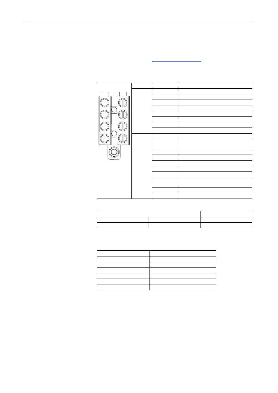
DC Input Precharge Control Wiring
If you are installing a DC input drive with a precharge interlock you must
make the following connections on the X50 terminal block from the
precharge circuit. Refer to
information.
Table 1.D X50 Terminal Block Connections
Table 1.E X50 Terminal Block Specifications
Table 1.F External Relay Contact Ratings
X50 Terminal Block Frame
Terminal
Description
9
1
Charge Relay Contact
2
Charge Relay Contact
5
Precharge Complete Signal (+24V DC)
6
Precharge Complete Signal (Common)
10, 11 & 13 3
Charge Relay Contact
4
Charge Relay Contact
1
Precharge Complete Signal (+24V DC)
2
Precharge Complete Signal (Common)
12 & 14
Power Module 1
3
Charge Relay Contact (Jumper to Power
Module 2 Terminal 4)
4
Charge Relay Contact
1
Precharge Complete Signal (+24V DC)
2
Precharge Complete Signal (Common)
Power Module 2
3
Charge Relay Contact
4
Charge Relay Contact (Jumper to Power
Module 1 Terminal 21)
1
Precharge Complete Signal (+24V DC)
2
Precharge Complete Signal (Common)
Wire Size Range
(1)
(1)
Maximum/minimum sizes that the terminal block will accept - these are not recommendations.
Torque
Maximum
Minimum
Recommended
6.0 mm
2
(10 AWG)
1.0 mm
2
(18 AWG)
0.8 N•m (7.0 lb•in)
Load
Resistance load (cos
φ
= 1)
Rated load
8 A at 250 VAC: 5 A at 30 VDC
Rated carry current
8 A
Max. switching voltage
250 VAC; 30 VDC, (400 VAC)
(1)
(1)
P level:
λ
60 = 0.1 x 10
–6
operations
Max. switching current
AC 8 A; DC 5 A
Max. switching power
2,000 VA; 150 W
Failure rate (reference value)
5 VDC 10 mA (for gold plating 0.35 µ min.)