Lifting and mounting frame 14 drives, Lifting and mounting frame 14 drives -8 – Rockwell Automation 20D PowerFlex 700H and 700S Frame 9-14 Drives Installation - A4 Size User Manual
Page 154
11-8
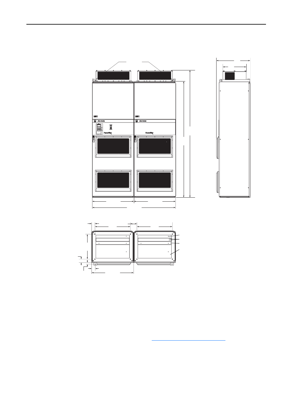
Frame 14 Installation
Figure 11.6 DC Input Drive Enclosure Code H (NEMA/UL Type 12, IP54) and W
(NEMA/UL Type 12, IP54 w/Conformal Coat)
Lifting and Mounting Frame
14 Drives
Enclosed Frame 14 Drives with DC Input
Enclosed Frame 14 drives with DC input are shipped with the control pan
mounted in the motor connection area of the left-hand enclosure. The
control pan must be moved from this location to a location in the adjacent
enclosure, away from the power connections.
Refer to Appendix B -
Lifting and Mounting Instructions
for detailed
instructions on lifting and mounting the drive. When you have completed
the instructions in Appendix B, continue with the installation as directed
below.
675
(26.6)
125 (5.0)
62.25
(2.5)
475
(1
8
.7)
65
(2.6)
3
0 (1.2)
6
8
.75 (2.7)
799.5 (
3
1.5)
675
(26.6)
22
3
2
(
88
)
662
(26)
454
(1
8
)
2276
(90)
1597 (6
3
.0)
Lifting Point
s
799.5 (
3
1.5)
799.5 (
3
1.5)
CLOSE
OPEN
Dimensions are in millimeters and (inches).
Wire entry for this enclosure is between two pieces of
soft foam. If the adjustable plate is slid back, a gap
develops between the foam pieces. Otherwise, the
foam acts as a loose gasket around the wires.
Stationary metal front bottom plate
Two pieces of soft foam taped to adjacent metal plates
Overlapping metal bottom plate (slightly adjustable)
Stationary metal back bottom plate