Rockwell Automation 20D PowerFlex 700H and 700S Frame 9-14 Drives Installation - A4 Size User Manual
Page 33
PowerFlex
®
700H Control Wiring
2-7
Auxiliary Power Supply Specifications
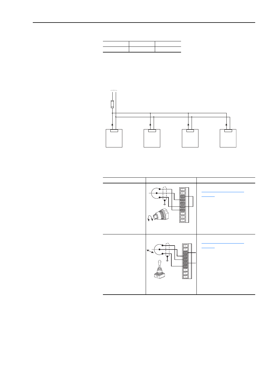
If 24V terminals of several drives are connected in parallel, we recommend
using a diode circuit to block current flow in the opposite direction. Reverse
current flow could damage the Control Board.
I/O Wiring Examples
Voltage
Current (Min)
Current (Max)
24V dc ± 15%
150 mA
250 mA
Input/Output
Connection Example
Required Parameter Changes
Potentiometer Unipolar
Speed Reference
(1)
10k Ohm Pot.
Recommended
(2k Ohm Minimum)
•
Set I/O configuration (refer to
Analog I/O Configuration on
page 2-6
).
•
Adjust Scaling:
Parameters 91 [Speed Ref A Hi] /
92 [Speed Ref A Lo] and 325
[Analog In 2 Hi] / 326 [Analog In 2
Lo]
•
View Results:
Parameter 002 [Commanded
Speed]
Joystick Bipolar Speed
Reference
±
10V Input
•
Set I/O configuration (refer to
Analog I/O Configuration on
page 2-6
).
•
Set parameter 190 [Direction Mode]
= 1 “Bipolar”
•
Adjust Scaling:
Parameters 91 [Speed Ref A Hi] /
92 [Speed Ref A Lo] and 325
[Analog In 2 Hi] / 326 [Analog In 2
Lo]
•
View Results:
Parameter 002 [Commanded
Speed]
:19
:20
From Auxiliary
Power Supply
:19
:20
:19
:20
:19
:20
24V dc
Power
24V dc
Common
3
4
6
6
7
3
6
4
7
5