Rockwell Automation 20D PowerFlex 700H and 700S Frame 9-14 Drives Installation - A4 Size User Manual
Page 63
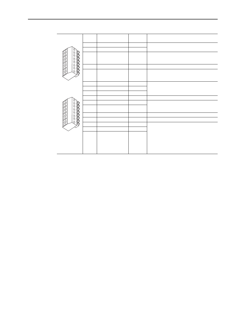
Control Wiring for PowerFlex 700S Drives with Phase II Control
4-5
Table G TB2 Terminals
Terminal Signal
Factory
Default
Description
1
24V DC Common (-)
NA
Drive supplied 24V DC logic input power
Rating: 300 mA maximum load
2
24V DC Source (+)
NA
3
Digital Output 1
24V DC Open Collector (sinking logic)
Rating: Internal Source = 150 mA max.
External Source = 750 mA
4
Digital Output 1/2 Com NA
Common for Digital Output 1 & 2
5
Digital Output 2
24V DC Open Collector (sinking logic)
Rating: Internal Source = 150 mA max.
External Source = 750 mA
6
Relay Output 3 (NC)
Relay contact output
Rating: 115V AC or 24V DC = 2 A max.
Inductive/Resistive
7
Relay Output 3 Com
NA
8
Relay Output 3 (NO)
9
Digital Input 1-3 Com
NA
Common for Digital Inputs 1-3
10
Digital Input 1
High speed 12V or 24V DC
(1)
, sinking
Load:15 mA at 24V DC
11
Digital Input 2
12
Digital Input 3
Load:15 mA at 24V DC sourcing
13
Digital Input 4-6 Com
NA
Common for Digital Inputs 4-6
14
Digital Input 4
Load: 10 mA at 24V DC sinking/sourcing
Load: 7.5 mA at 115V AC
Note: The 115 VAC Digital Inputs can withstand 2
milliamps of leakage current without turning on. If an
output device has a leakage current greater than 2
milliamps a burden resistor is required. A 68.1K ohm
resistor with a 0.5 watt rating should be used to keep
the 115 VAC output below 2 milliamps.
15
Digital Input 5
16
Digital Input 6
HW Enable
(1)
Digital Inputs 1 and 2 are configured for 12V or 24V DC via DIP switches S3-1 and S3-2, respectively. 24V DC is the default setting.
1
2
3
4
5
6
7
8
9
10
11
12
13
14
15
16