Rockwell Automation 20D PowerFlex 700H and 700S Frame 9-14 Drives Installation - A4 Size User Manual
Page 46
3-8
Control Wiring for PowerFlex 700S Drives with Phase I Control
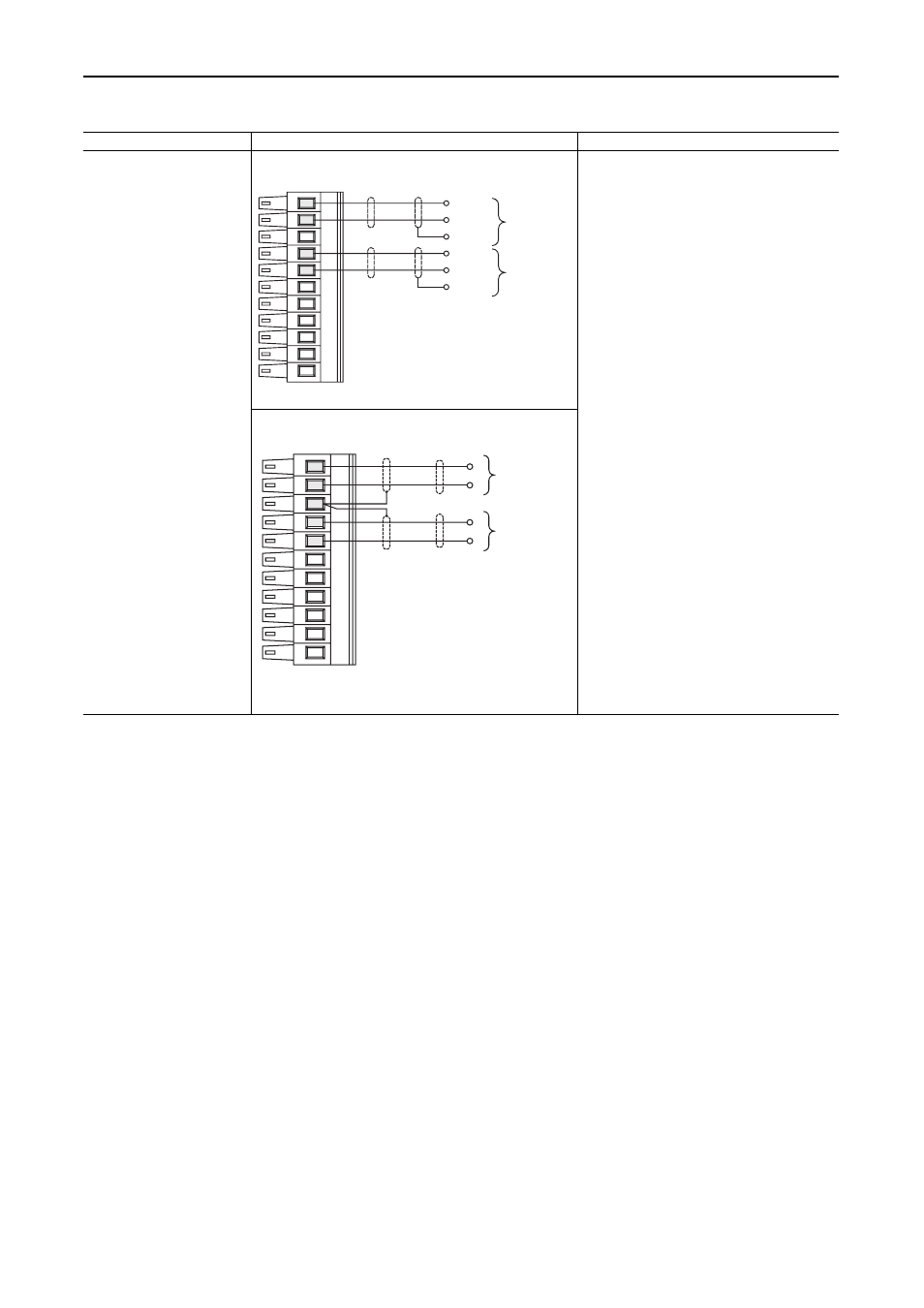
Figure 3.2 TB1 - Row B (Bottom) Wiring Examples
Input/Output
Connection Example
Required Parameter Changes
Analog Inputs
+/-10V dc or +/-1.0V dc
(DIP switch selectable)
Terminate shields at the analog
source if analog common is
available
Used for Speed Reference and
Speed Trim
Analog Inputs for Speed Reference and Speed Trim - shield
terminated at the source
Example: Using Analog Input 1 as 0-10V speed
reference
•
Adjust Parameter 803 [Anlg In1 Offset] so that
the minimum analog signal creates the
minimum speed reference (if the minimum input
is 0V dc and the minimum speed reference is
zero, enter a value of zero)
•
Adjust Parameter 802 [Anlg In1 Scale] so that
the maximum analog signal creates the
maximum speed reference (if the maximum
input is 10V dc and the maximum speed
reference is motor base speed, enter a value of
0.1)
•
Send the data to the Speed Reference
parameter Par 10 [Speed Ref 1] (the
destination) linked to Par 800 [Anlg In1 Data]
(the source)
•
Select 1 - “Spd Ref 1” as the active speed ref in
Par 16 [Speed Ref Sel]
•
In Par 153 [Control Options] set bit 0 “Bipolar
SRef” = 1
Example: Using Analog Input 2 as -10 to +10V
speed trim @ 10%:
•
Adjust Parameter 809 [Anlg In2 Offset] so that
the minimum analog signal creates the
minimum speed trim (if the minimum input is 0V
dc and the minimum trim is zero, enter a value
of zero)
•
Adjust Parameter 808 [Anlg In2 Scale] so that
the maximum analog signal creates the
maximum speed trim (if the maximum input is
10V dc and the maximum speed trim is 10%,
enter a value of 0.01)
•
Send the data to the Par 12 [Speed Ref 2] (the
destination) linked to Par 806 [Anlg In2 Data]
(the source)
•
Use Par 10 [Spd Ref 1] as the active speed
reference and Par 12 [Spd Ref 2] as the speed
trim. Set Par 16 [Speed Ref Sel] = 3 - “Spd Ref
3”
Analog Inputs for Speed Reference and Speed Trim - shield
terminated at the drive
11
10
8
7
-
+
Common
(Return)
Analog Input #1
Speed
Reference
-
+
Common
(Return)
Analog Input #2
Speed
Trim
11
10
8
7
-
+
Analog Input #1
Speed
Reference
-
+
Analog Input #2
Speed
Trim