Rockwell Automation 20D PowerFlex 700H and 700S Frame 9-14 Drives Installation - A4 Size User Manual
Page 35
PowerFlex
®
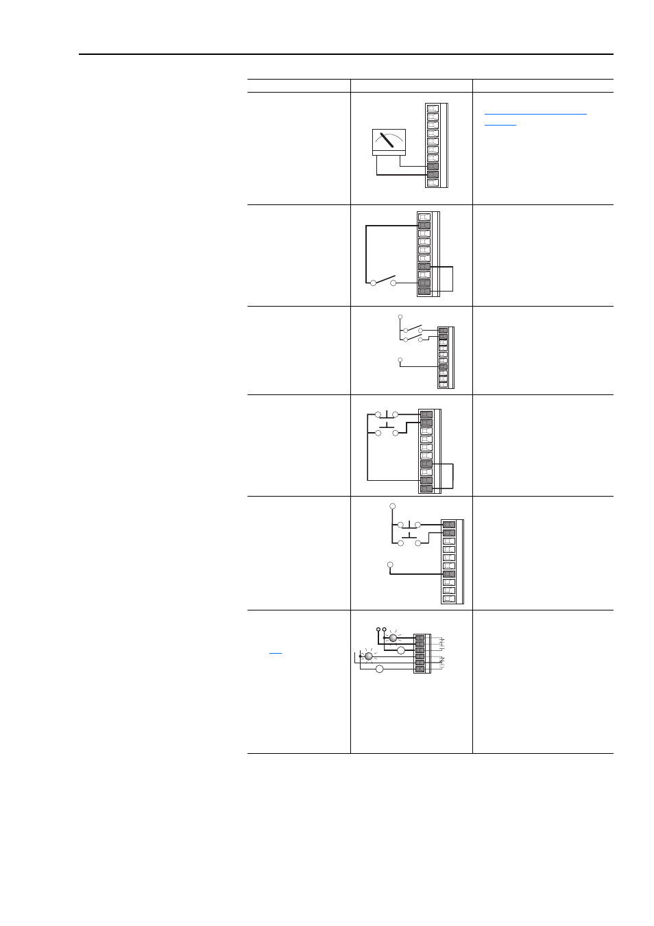
700H Control Wiring
2-9
Analog Output
±
10V, 4-20 mA Bipolar
+10V Unipolar
(shown)
•
Set I/O configuration (refer to
Analog I/O Configuration on
page 2-6
).
•
Configure with Parameter 340 [Anlg
Out Config]
•
Select Source Value:
Parameter 384 [Digital Out1 Sel]
•
Adjust Scaling:
Parameters 343 [Analog Out1 Hi] /
344 [Analog Out1 Lo]
2-Wire Control
Non-Reversing
(2)
24V dc internal supply
•
Disable Digital Input:#1:
Parameter 361 [Digital In1 Sel] = 0
“Not Used”
•
Set Digital Input #2:
Parameter 362 [Digital In2 Sel] = 7
“Run”
•
Set Direction Mode:
Parameter 190 [Direction Mode] = 0
“Unipolar”
2-Wire Control
Reversing
External supply
(I/O Board dependent)
•
Set Digital Input:#1:
Parameter 361 [Digital In1 Sel] = 8
“Run Forward”
•
Set Digital Input #2:
Parameter 362 [Digital In2 Sel] = 9
“Run Reverse”
3-Wire Control
Internal supply
•
No Changes Required
3-Wire Control
External supply
(I/O Board dependent).
Requires 3-wire functions
only ([Digital In1 Sel]).
Using 2-wire selections will
cause a type 2 alarm.
•
No Changes Required
Digital Output
Relays shown in powered
state with drive faulted. See
page
2 relays at terminals 24-26.
•
Select Source to Activate:
Parameters 380 [Digital Out1 Sel] /
384 [Digital Out2 Sel]
Input/Output
Connection Example
Required Parameter Changes
8
9
+
–
12
17
20
19
Stop-Run
12
17
11
Run Rev.
Run Fwd.
115V/
+24V
Neutral/
Common
12
17
20
11
19
Start
Stop
12
17
11
Start
Stop
115V/
+24V
Neutral/
Common
21
24
Power Source
Fault
NOT Fault
NOT Run
Run
or
22
25
23
26