Rockwell Automation 20D PowerFlex 700H and 700S Frame 9-14 Drives Installation - A4 Size User Manual
Page 202
B-6
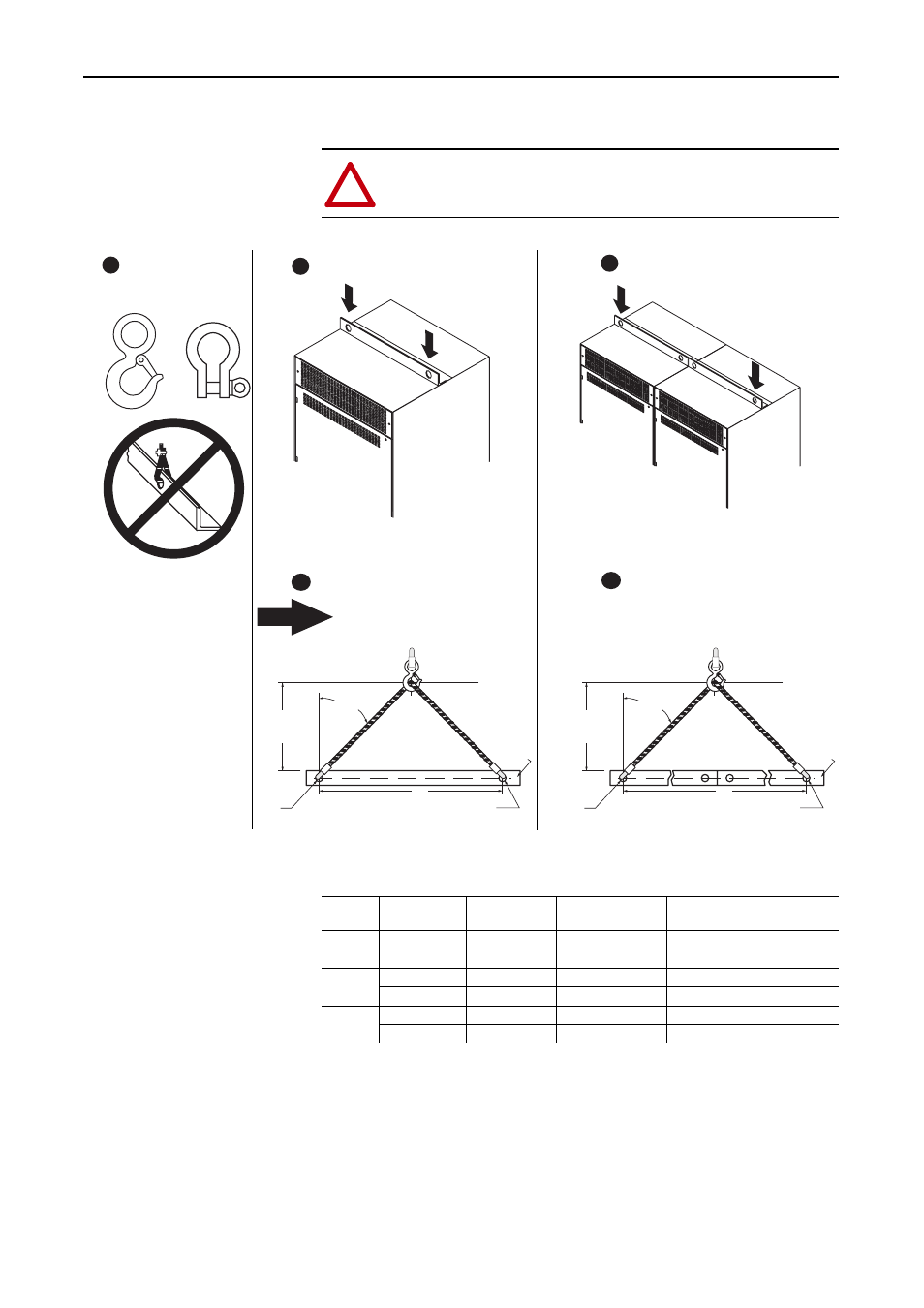
Lifting and Mounting Instructions
Directions for Lifting Drives in an MCC Enclosure (Code “B”)
Table B.E Frame 10 - 12 Approximate Drive and MCC Style Enclosure (Code “B”)
Weights
!
ATTENTION: Always use slings with load rated safety hooks
or shackles.
A
TO BE U
S
ED
A
1/2 A
or more
NEVER
EXCEED
45°
LIFT
POINT
LIFT
ANGLE
LIFT
HOLE
LIFT
HOLE
A
1/2 A
or more
NEVER
EXCEED
45°
LIFT
POINT
LIFT
ANGLE
OUT
S
IDE
LIFT
HOLE
OUT
S
IDE
LIFT
HOLE
TIP: The height (of
the lift point) above
the lift angle should
be at least one half
"A" (the distance
between lift holes).
This assures an
angle of less than
45° with the vertical.
C
B
All Size Drives
Frame 10 and 11 Size Drives
Frame 12 Size Drives
B
C
Frame 10 and 11 Size Drives
Frame 12 Size Drives
Frame
Voltage Class
Drive Rating
Amps
Drive & Enclosure
Weight kg (lbs.)
Drive, Enclosure & Packaging
Weight kg (lbs.)
10
400V AC
385 - 500
454 (1100)
522 (1150)
600V AC
261-416
449 (990)
480 (1058)
11
400 V AC
590 - 730
696 (1535)
719 (1585)
600 V AC
460 - 590
640 (1411)
661 (1457)
12
400 V AC
820 - 1030
966 (2130)
989 (2180)
600 V AC
650 - 820
888 (1958)
909 (2003)