Rockwell Automation 20D PowerFlex 700H and 700S Frame 9-14 Drives Installation - A4 Size User Manual
Page 28
2-2
PowerFlex
®
700H Control Wiring
700H Control Circuit Board Designations
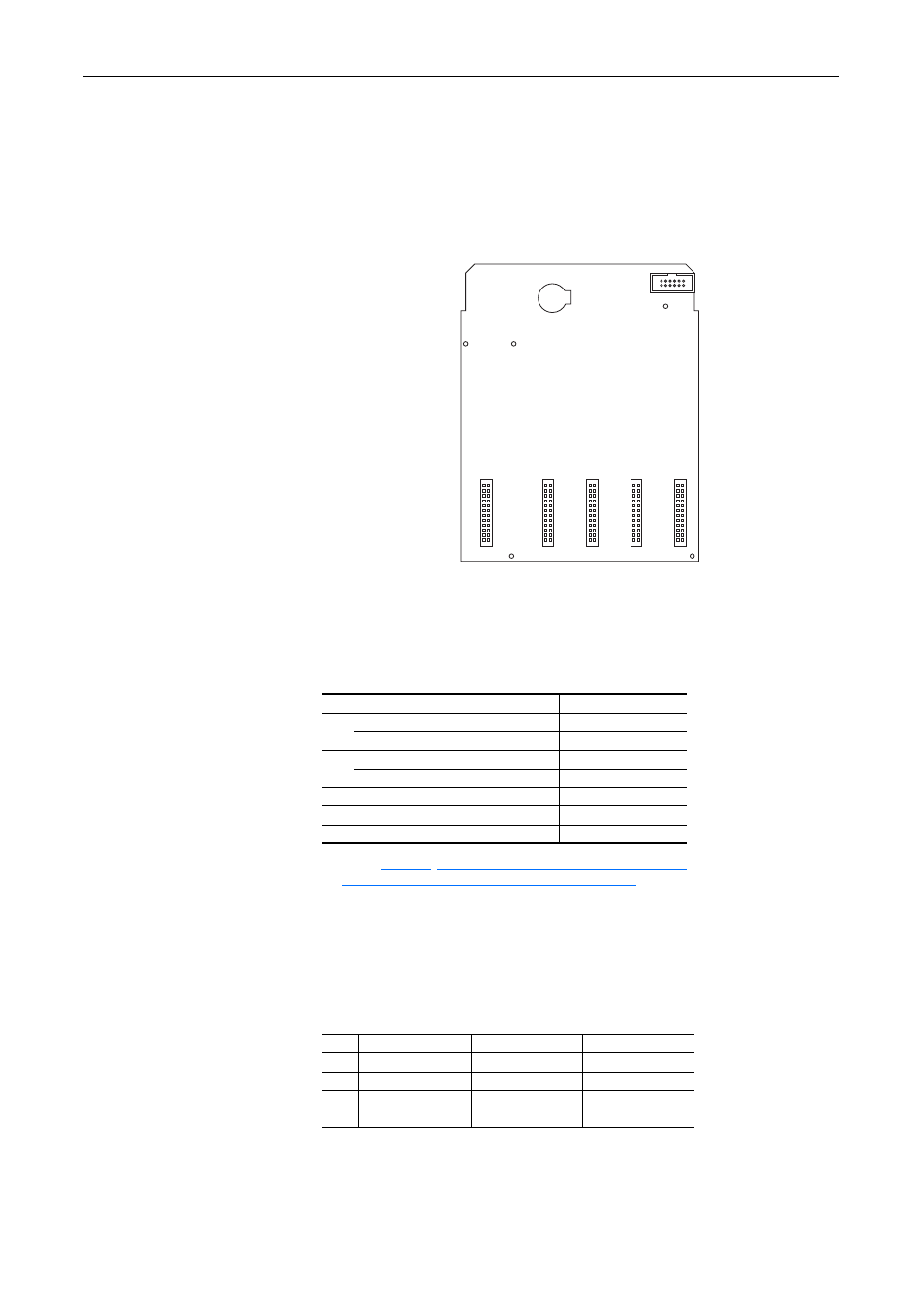
The PowerFlex 700H control circuit board allows for a variety of I/O boards
to be installed depending upon your application. Each option I/O circuit
board is described below.
Figure 2.1 PowerFlex 700H Control Circuit Board
Important: The boards identified in the table below can only be installed in
the designated slot. Boards and slots are not interchangeable.
Table 2.C Control Board Slot Designations
Drive Catalog Numbers for 700H Control I/O Board Options
The following codes are designated in position 15 of the drive catalog string
to indicate the desired combination of 700H I/O option boards supplied with
the drive:
Slot Used for Circuit Board . . .
Part No.
A
24V DC Digital Input with Analog I/O
20C-DA1-A
115V AC Digital Input with Analog I/O
20C-DA1-B
B
24/115V Digital Output
20C-DO1
24V DC Digital Gate Disable option
(1)
(1)
Refer to
Instructions for ATEX Approved PowerFlex 700H Drives
in Group II Category (2) Applications with ATEX Approved Motors
for more
information on installing and configuring the Gate Disable option board.
20C-DG1
C
(Not Used)
–
D
(Not Used)
–
E
DPI Option Board
20C-DPI1
Code Board in Slot A
Board in Slot B
Board in Slot E
A
20C-DA1-A
20C-DO1
20C-DPI1
B
20C-DA1-B
20C-DO1
20C-DPI1
G
20C-DA1-A
20C-DG1
20C-DPI1
N
none
none
20C-DPI1
Slot
A
B
C
D
E