Removing the protective covers – Rockwell Automation 20D PowerFlex 700H and 700S Frame 9-14 Drives Installation - A4 Size User Manual
Page 159
Frame 14 Installation
11-13
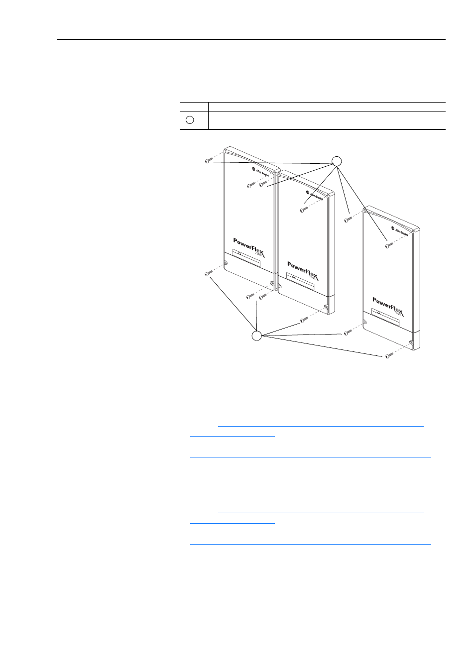
Removing the Protective Covers
You must remove the protective covers to gain access to the Converter
unit(s).
Installation on an Ungrounded Distribution System or High Resistive
Ground
•
Must move the common mode jumper(s) to the disconnected position -
refer to
"Move the Common Mode Jumper(s) to the Disconnected
.
•
Should insulate terminal X4 on the Rectifier circuit board - refer to
"Insulate Terminal X4 on the Rectifier Circuit Board" on page 11-15
If you are installing a 600/690V AC input drive on an ungrounded
distribution system or high resistive ground, you:
•
Must move the common mode jumper(s) to the disconnected position -
refer to
"Move the Common Mode Jumper(s) to the Disconnected
.
•
Must insulate terminal X4 on the Rectifier circuit board - refer to
"Insulate Terminal X4 on the Rectifier Circuit Board" on page 11-15
Task
Description
Remove the four M5 POZIDRIV screws that secure each of the two or three main and
bottom protective covers to the drive, then remove the protective covers.
A
DC B
US CONDUCT
ORS AND CAP
ACIT
ORS
OPERA
TE A
T HIGH
VO
LTA
GE.
REMO
VE PO
WER
AND
WA
IT 5 MINUTES BEFORE S
ER
VICING
DA
NGER
!
DC B
US CONDUCT
ORS AND CAP
ACIT
ORS
OPERA
TE A
T HIGH
VO
LTA
GE.
REMO
VE PO
WER
AND W
AIT 5 MINUTES BEFORE SER
VICING
DA
NGER
!
DC B
US CONDUCT
ORS AND CAP
ACIT
ORS
OPERA
TE A
T HIGH
VO
LTA
GE.
REMO
VE PO
WER
AND W
AIT 5 MINUTES BEFORE SER
VICING
DA
NGER
!
A
A