Rockwell Automation 20D PowerFlex 700H and 700S Frame 9-14 Drives Installation - A4 Size User Manual
Page 168
11-22
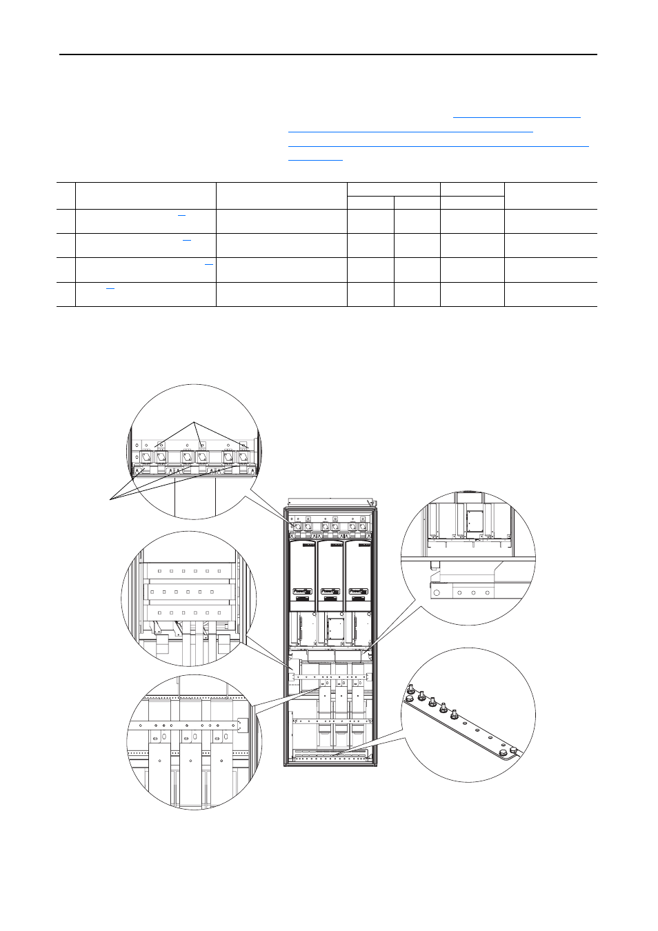
Frame 14 Installation
Important: Once power wiring has been completed, the protective covers
must be installed before energizing the drive. Installation is in
reverse order of removal (refer to
Covers from the Converter Unit(s)" on page 11-10
"Removing the Protective Covers from the Inverter Units" on
page 11-16
.)
Table 11.B Power Terminal Specifications
Figure 11.10 1500A Drive Terminal Locations
No. Name
Description
Wire Size Range
(1)(2)
Torque
Terminal Bolt Size
(3)(4)
Maximum
Minimum
Recommended
➊
Input Power Terminal Block
L1, L2, L3
Input power
300 mm
2
(600 MCM)
2.1 mm
2
(14 AWG)
40 N•m
(354 lb•in)
M12
➋
Output Power Terminal Block
U/T1, V/T2, W/T3
Motor connections
300 mm
2
(600 MCM)
2.1 mm
2
(14 AWG)
40 N•m
(354 lb•in)
M12
➌
SHLD Terminal, PE, Motor Ground
Terminating point for wiring shields 300 mm
2
(600 MCM)
2.1 mm
2
(14 AWG)
40 N•m
(354 lb•in)
M10
➍
DC Bus
(3 Terminals; DC–, DC+)
DC input or external brake
300 mm
2
(600 MCM)
2.1 mm
2
(14 AWG)
40 N•m
(354 lb•in)
M12
(1)
Maximum/minimum sizes that the terminal block will accept - these are not recommendations.
(2)
Do Not exceed maximum wire size. Parallel connections may be required.
(3)
These connections are bus bar type terminations and require the use of lug type connectors.
(4)
Apply counter torque to the nut on the other side of terminations when tightening or loosening the terminal bolt in order to avoid damage to the terminal.
U/T1
V/T2
W/T3
Side View
U/T1
V/T2
W/T3
L3
L1
L2
Ground Terminals
DC Bus Terminals
Output Power Terminals
without du/dt Filters
Output Power Terminals
with du/dt Filters
➊
➌
➋
➋
Input Power
Terminals
DC–
(Front Terminals)
➍
DC+
(Back Terminals)
Center Enclosure Shown