Rockwell Automation 20D PowerFlex 700H and 700S Frame 9-14 Drives Installation - A4 Size User Manual
Page 42
3-4
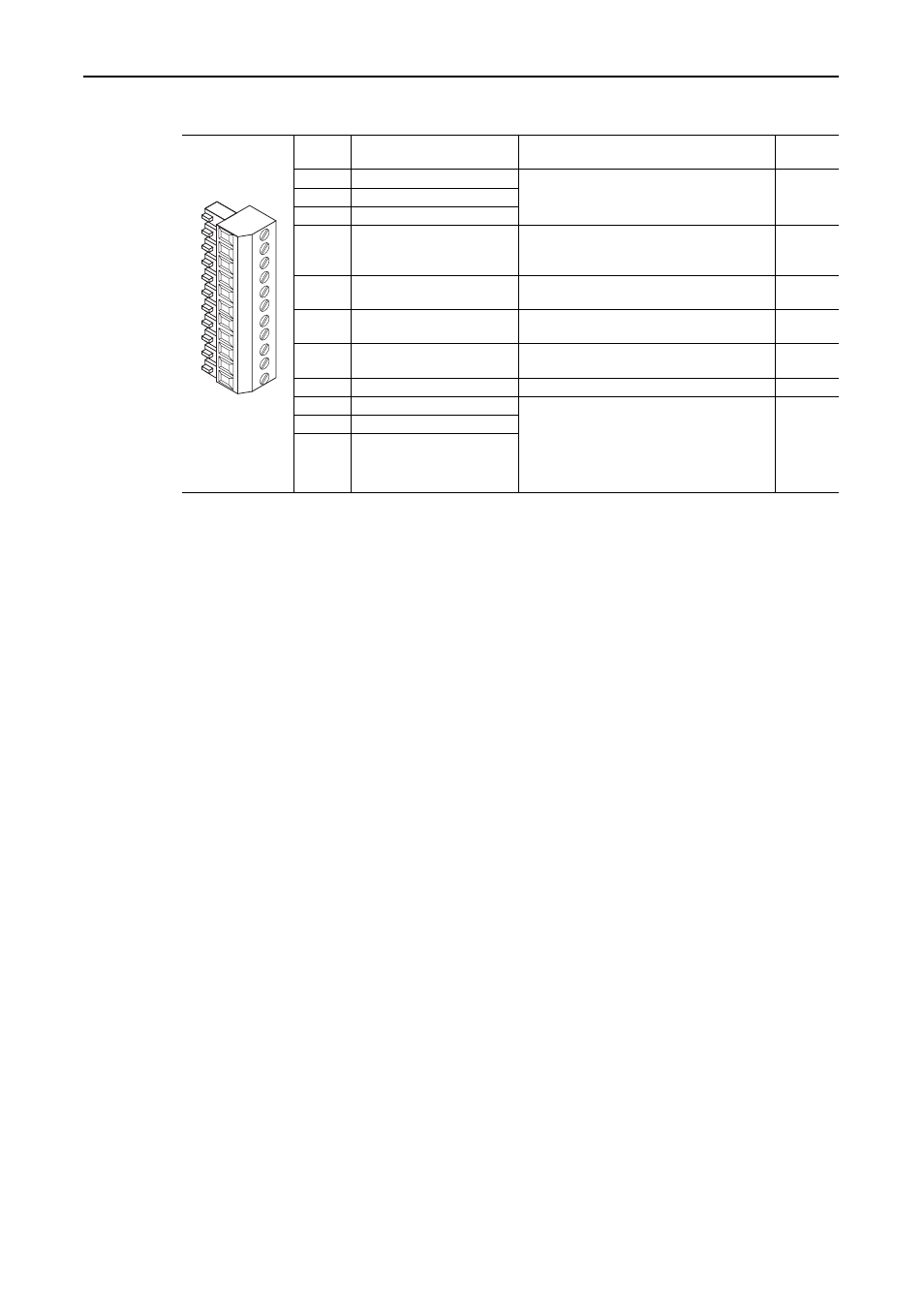
Control Wiring for PowerFlex 700S Drives with Phase I Control
Table 3.D TB1 - Row T (Top) Terminals
Terminal Signal
Description
Related
Parameter
T11
Power Supply 24V dc Return (-) Power and common for precharge and enable
inputs.
(1)
Inputs may sink or source.
(2)
Rating: 100 mA maximum.
T10
Power Supply 24V dc (+)
T9
Logic Common
T8
Digital Input 1
Default = Precharge
For common DC bus drives. Must be high, for
drive to complete the precharge cycle.
Load: 20 mA at 24V dc.
824, 826,
827, 828,
829, 838
T7
Enable Input
Must be high for drive to run.
Load: 20 mA at 24V dc.
824, 825
T6
Digital Output 1
24V dc open collector (sinking logic) output.
Rating: 25 mA maximum.
824, 843,
844
T5
Digital Output 2
24V dc open collector (sinking logic) output.
Rating: 25 mA maximum.
824, 845,
846
T4
Digital Output Return
Return for Digital outputs 1 and 2.
T3
Thermistor Input
Used only in FOC2 mode with approved motor for
temperature adaptation.
Refer to Appendix A, “Supplemental Information”,
in publication 20D-UM001..., User Manual -
PowerFlex 700S High Performance AC Drive,
Phase I Control, for approved motors.
485
T2
Thermistor Input Return
T1
Thermistor Shield
(1)
The drive’s 24V dc power supply supports only on-board digital inputs. Do not use it to power circuits outside of the drive.
(2)
Refer to wiring examples of sinking and sourcing outputs.
11
10
9
8
7
6
5
4
3
T1
2