Rockwell Automation 20D PowerFlex 700H and 700S Frame 9-14 Drives Installation - A4 Size User Manual
Page 231
Instructions for ATEX Approved PowerFlex 700H Drives in Group II Category (2) Applications with ATEX Approved Motors
F-3
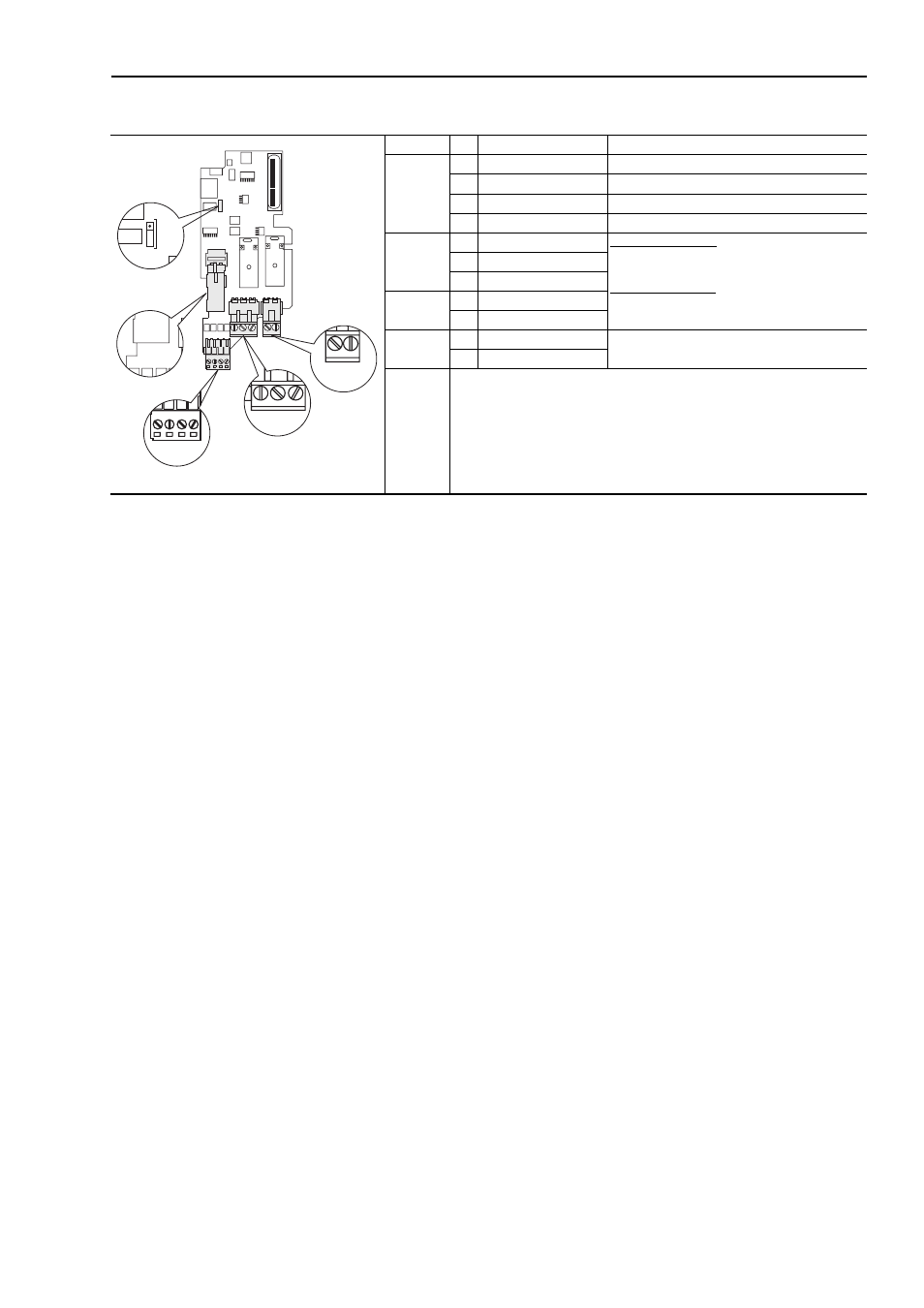
Table F.A Terminal Descriptions
Important: The drive will not run unless one of the following conditions is
met:
– A wire must be installed in the hardware thermistor input
(X7-28 and X7-29) and the thermistor short circuit
supervisor jumper X10 must be installed in the OFF
position.
OR
– A thermistor must be installed in the hardware thermistor
input (X7-28 and X7-29).
Term. Blk. No. Signal
Description
X5
1
SD1+
Isolated Disable input 1 +24V +/-20% 10... 15mA
2
SD1–
Virtual GND 1
3
SD2+
Isolated Disable input 2 +24V +/-20% 10... 15mA
4
SD2–
Virtual GND 2
X2
21
Digital Out 1 - N.C.
Max. Resistive Load:
240V ac / 30V dc - 1200VA, 150W
Max. Current: 5A, Min. Load: 10mA
Max. Inductive Load:
240V ac / 30V dc - 8400VA, 105W
Max. Current: 3.5A, Min. Load: 10mA
22
Digital Out 1 Common
23
Digital Out 1 - N.O.
X3
25
Digital Out 2 Common
26
Digital Out 2 N.O.
X7
28
TI1+
Thermistor input: R
trip
≥
4.0 k
Ω
(PTC)
29
TI1–
21 22 23
25 26
1 2 3 4
28 29
ON OFF
X10
X5
X2
X3
X7