Rockwell Automation 20D PowerFlex 700H and 700S Frame 9-14 Drives Installation - A4 Size User Manual
Page 65
Control Wiring for PowerFlex 700S Drives with Phase II Control
4-7
Table I TB1 Terminals— Analog Wiring Examples
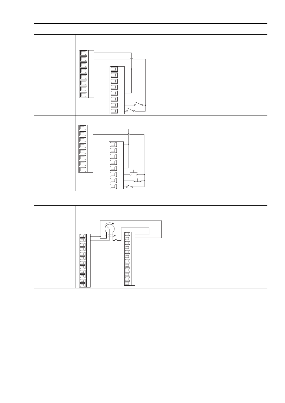
Digital Inputs
24V DC
Sourcing Digital Inputs - Internal Power Supply, 2-Wire Control Required Parameter Changes
•
Set the value of Par 829 [Dig In5 Sel] to a value of 7 -
“Run”
•
Par 153 [Control Options], bit 8 “3WireControl” will
automatically be off (0) for 2-wire control.
•
Set Par 168 [Normal Stop Mode] for the desired
stopping mode:
0 = Ramp Stop
1 = CurLim Stop
2 = Coast Stop
Digital Inputs
24V DC
Sourcing Digital Inputs- Internal Power Supply, 3-Wire
•
Set the value of Par 829 [Dig In5 Sel] to a value of 14 -
“Normal Stop”
•
Set Par 828 [Dig In4 Sel] to a value of 5 - “Start”
•
Par 153 [Control Options], bit 8 “3WireControl” will
automatically be off (0) for 2-wire control.
•
Set Par 168 [Normal Stop Mode] for the desired
stopping mode:
0 = Ramp Stop
1 = CurLim Stop
2 = Coast Stop
Input/Output
Connection Example
24V dc
Com
Run
Enable
1
2
3
4
5
6
7
8
9
10
11
12
13
14
15
16
24V dc
Com
Start
Enable
Stop
9
10
11
12
13
14
15
16
1
2
3
4
5
6
7
8
Input/Output
Connection Example
0-10V Analog Input
0-10V Analog Input - Internal Source
Required Parameter Changes
na
1
2
3
4
5
6
7
8
9
10
11
12
13
14
15
16
17
18
19
20
21
22
23
24