Axislink settings for standard axislink operation – Rockwell Automation 999 IMC S Class Compact Motion Controller (Cat. No. 4100-999-122) User Manual
Page 76
4-34
Installation and Hookup
Publication 999-122 - January 1997
The AxisLink option can be operated in either of two configurations
depending upon the cable length required between controllers. Refer
to the AxisLink specifications in this manual for more information on
the differences between the two configurations. The standard
configuration is used for daisy-chain cabling with a maximum
end-to-end distance of 1 to 25 meters (3 to 82 feet) and the extended
configuration for daisy-chain cabling with a maximum end-to-end
distance of 25 to 125 meters (82 to 410 feet). To use the AxisLink option
in its extended configuration, the IMC-S/23x-L or IMC-S/23x-RL
controller requires a firmware version of V3.2 or later for extended
length and V3.5 or later for extended node (extended node also requires
GML V3.9 or later). For both configurations, there is a 1 m (3 ft)
minimum cable length between AxisLink nodes. The AxisLink option
switch setting, termination resistors, and cabling are different for the
two configurations and must be correct for proper AxisLink operation
in the intended configuration.
Important: To use extended length mode, you need firmware V3.2 or
later. To use extended node, you need V3.5 or later.
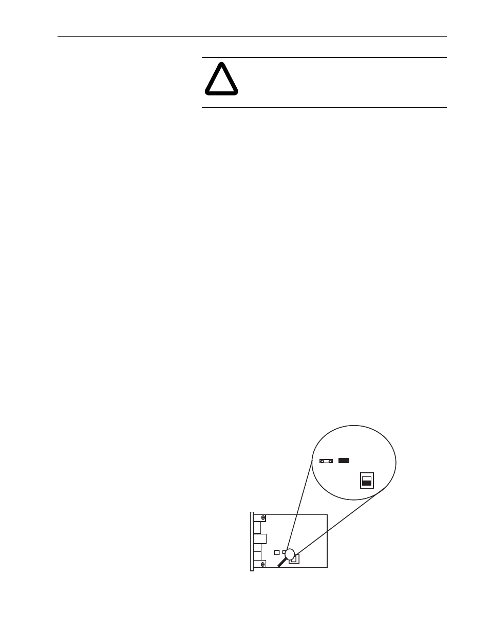
AxisLink Settings for Standard AxisLink Operation
Switch 1 (SW1) on the AxisLink board must be set to the
non-EXTENDED setting (toward the edge of the board).
Jumper 6 (J6), labeled STD on the board, must be in place across both
J6 pins if using onboard cable termination. Jumper 5 (J5) on the board
should not be connected.
!
ATTENTION: Even though AxisLink and RIO use
the same cable, connections are not interchangeable.
Do not mix RIO and AxisLink connections or neither
link will work properly.
XTEND
STD
J6
EXTENDED
SW1
J5