Installing the imc-s/23x – Rockwell Automation 999 IMC S Class Compact Motion Controller (Cat. No. 4100-999-122) User Manual
Page 48
4-6
Installation and Hookup
Publication 999-122 - January 1997
Installing the IMC-S/23x
The IMC-S/23x should be mounted to a panel inside an electrical
cabinet or enclosure. For best performance, it should be mounted as
close as practical to the servo drives with which it is being used. This
minimizes the length of cable required to interconnect the units, thus
minimizing the risk of electrical noise pickup. See the Introduction
section of this manual for mounting and clearance dimensions.
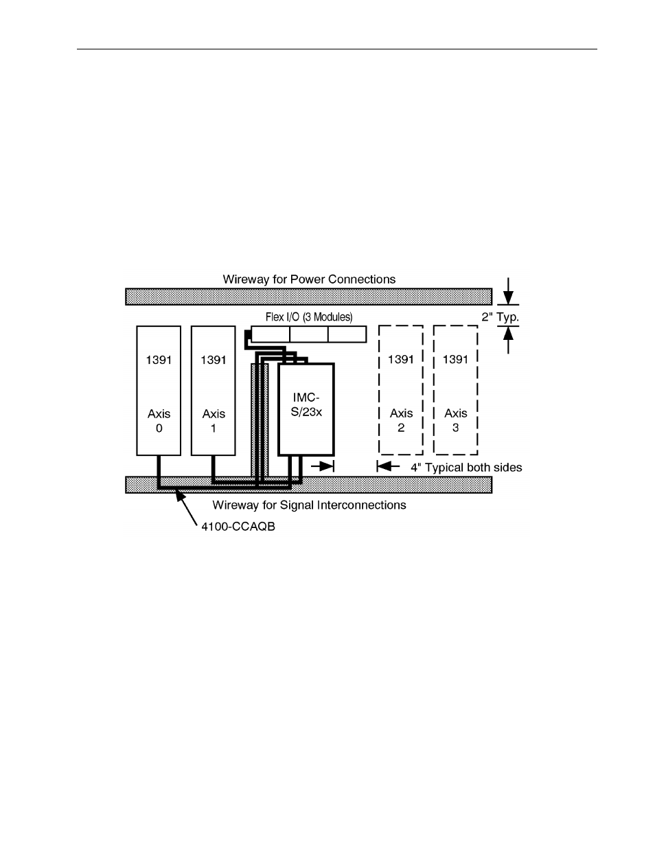
The recommended panel layout for using the IMC-S/23x with
Allen-Bradley 1391B-ES or 1391-DES AC servo drives is shown
below. Panel layouts for use with other servo drives should be similar.
Be sure to keep the power and signal wires segregated in separate
wireways for maximum noise immunity.
Each axis of the IMC-S/23x connects to a 1391 drive via a
4100-CCAQB pre-engineered cable assembly. Both ends of this cable
assembly are terminated in the appropriate mating connectors for the
motion controller and the drive. The 4100-CCAQB cable assembly
replaces both the 4100-CCSxxF and the 4100-CCAxxF when used with
a 1391B-ES or 1391-DES servo drive. Axis-specific dedicated I/O not
required by the servo drive (home input, overtravel inputs, drive fault
input, and registration input) are available via 15 foot (4.5 meter) flying
leads for termination to user devices or a user-supplied terminal block.