Calibrating the header float sensor – MacDon M205 Operators Manual User Manual
Page 111
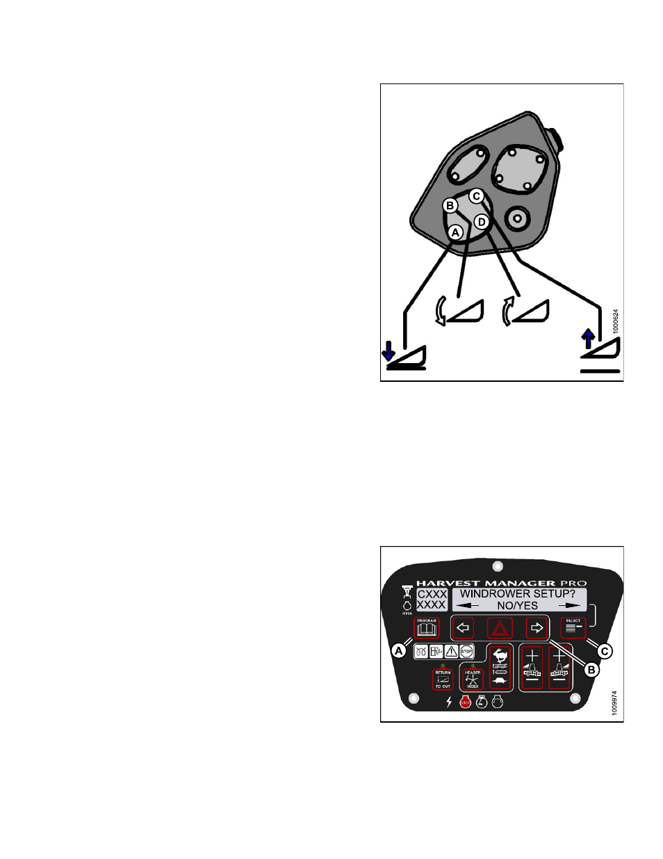
8. Press and hold HEADER TILT RETRACT (D) button
on GSL.
• CALIBRATING TILT is displayed on the upper line.
• RETRACT TILT HOLD is displayed on the
lower line.
NOTE:
The word HOLD will flash during calibration. HEADER
TILT COMPLETE will display on the lower line once
calibration is complete.
9. Release HEADER TILT RETRACT (D) button.
• TO CALIBRATE SELECT is displayed on the
upper line.
• HEADER TILT is displayed on the lower line.
10. Press right arrow to select next header sensor
calibration or STOP & EXIT. Press SELECT.
Refer to
Calibrating the Header Height Sensor, page
or
Calibrating the Header Float Sensor, page 95
.
11. Press PROGRAM to exit Programming Mode.
Figure 3.90: Header Tilt Controls on Ground
Speed Lever
Calibrating the Header Float Sensor
NOTE:
• Header MUST be attached to the windrower to perform this procedure. The cab display module (CDM)
automatically adjusts its programming for each header. For more information, refer to
.
• The Operator can use the left or right FLOAT buttons on the cab display module (CDM) to perform this procedure.
1. Turn ignition key to RUN, or start the engine. Refer to
.
2. Press PROGRAM (A) and SELECT (C) on cab display
module (CDM) to enter Programming Mode.
• WINDROWER SETUP? is displayed on the
upper line.
3. Press SELECT (C) until CALIBRATE SENSORS? is
displayed on the upper line.
• NO/YES is displayed on the lower line.
Figure 3.91: CDM Programming Buttons
169887
95
Revision A