Setting up channels – Teledyne LeCroy WaveRunner 6 Zi and 12-Bit HRO Getting Started Manual User Manual
Page 70
WaveRunner 6 Zi and 12-Bit HRO
62
922136-00 Rev A
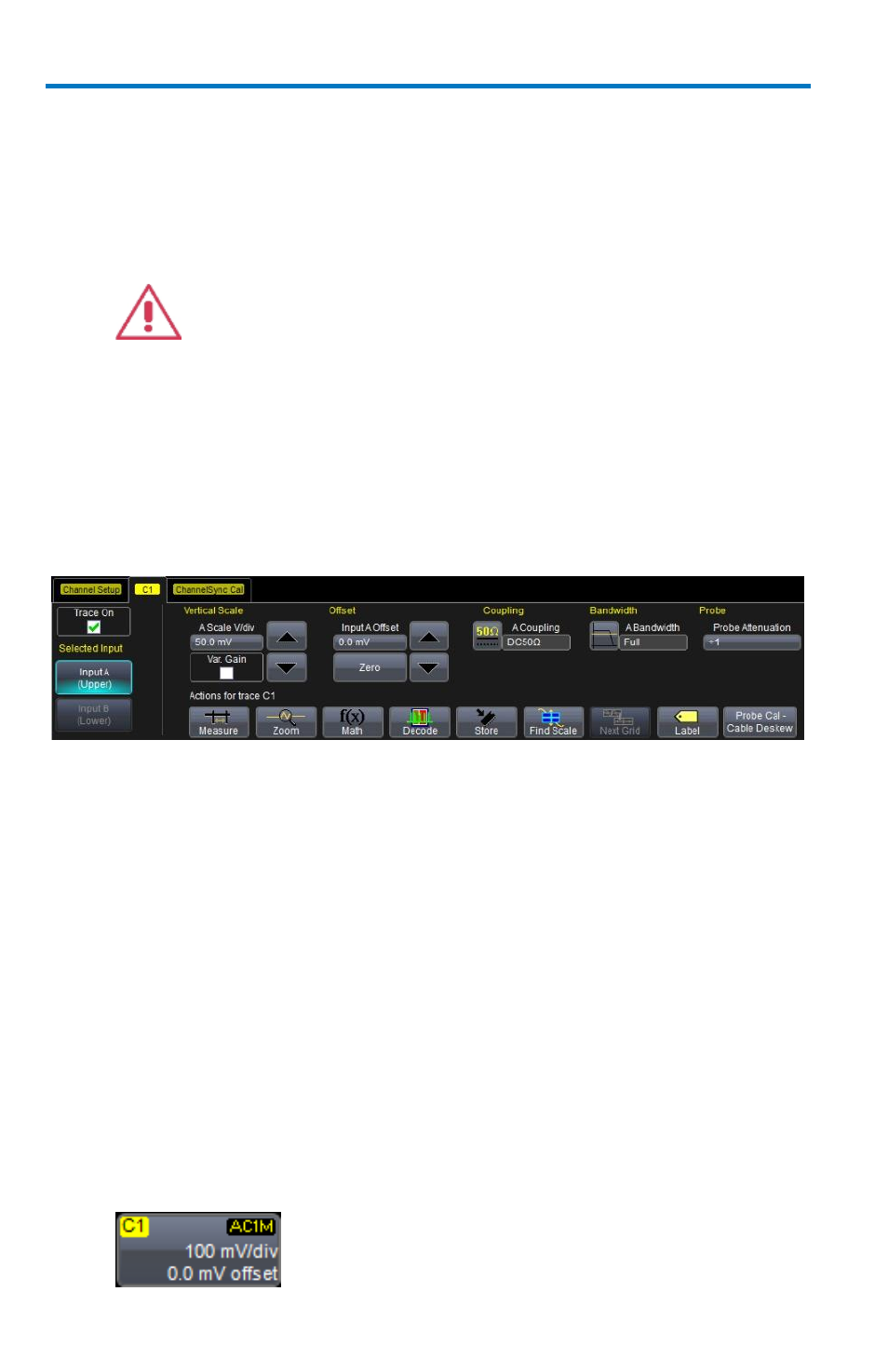
Coupling - The maximum input voltage depends on the input used.
Values are displayed on the front of the oscilloscope. Whenever the
voltage exceeds this limit, the coupling mode automatically switches
from DC 50 Ω to GROUND. You then have to manually reset the
coupling to DC 50 Ω.
CAUTION.While the unit does provide this protection,
damage can still occur if extreme voltages are applied
Bandwidth - Each oscilloscope contains only the Full selection and
those bandwidths less than the rated oscilloscope bandwidth. Anti-
aliasing filters are applied to limit bandwidth at lower sample rates,
regardless of bandwidth limit selection.
Probe - Teledyne LeCroy's ProBus, ProLink, and 2.92 mm system
automatically senses probes and sets their attenuation for you. For
each channel, the probe attenuation can also be set manually.
Setting Up Channels
1. Touch Vertical → Channelx Setup... from the menu bar.
2. Touch inside the Trace On checkbox to display the trace.
3. On pertinent model oscilloscopes, under Selected Input, touch the
Input A (Upper) button or Input B (Lower) button. Otherwise, no
Selected Input buttons are provided.
4. Turn the V
ERTICAL
G
AIN
front panel knob for the selected channel.
OR
Touch inside the Volts/Div field and enter a value. Click the keypad
button to enter a value using the pop-up keypad, or use the
up/down arrows.
The set voltage is shown on the trace descriptor label and in the
Volts/Div field in the dialog.