2 current monitor and variable monitor – IAI America PSEL User Manual
Page 60
50
Part 1 Installation
6.7.2 Current Monitor and Variable Monitor
By setting other parameter Nos. 49 and 50 appropriately, the optional panel unit can be used to monitor
either current levels or variables.
(1) Current
monitor
Currents of up to four axes having continuous axis numbers can be monitored.
Parameter settings
Other parameter No. 49 = 1
Other parameter No. 50 = Smallest axis number among the axes to be monitored
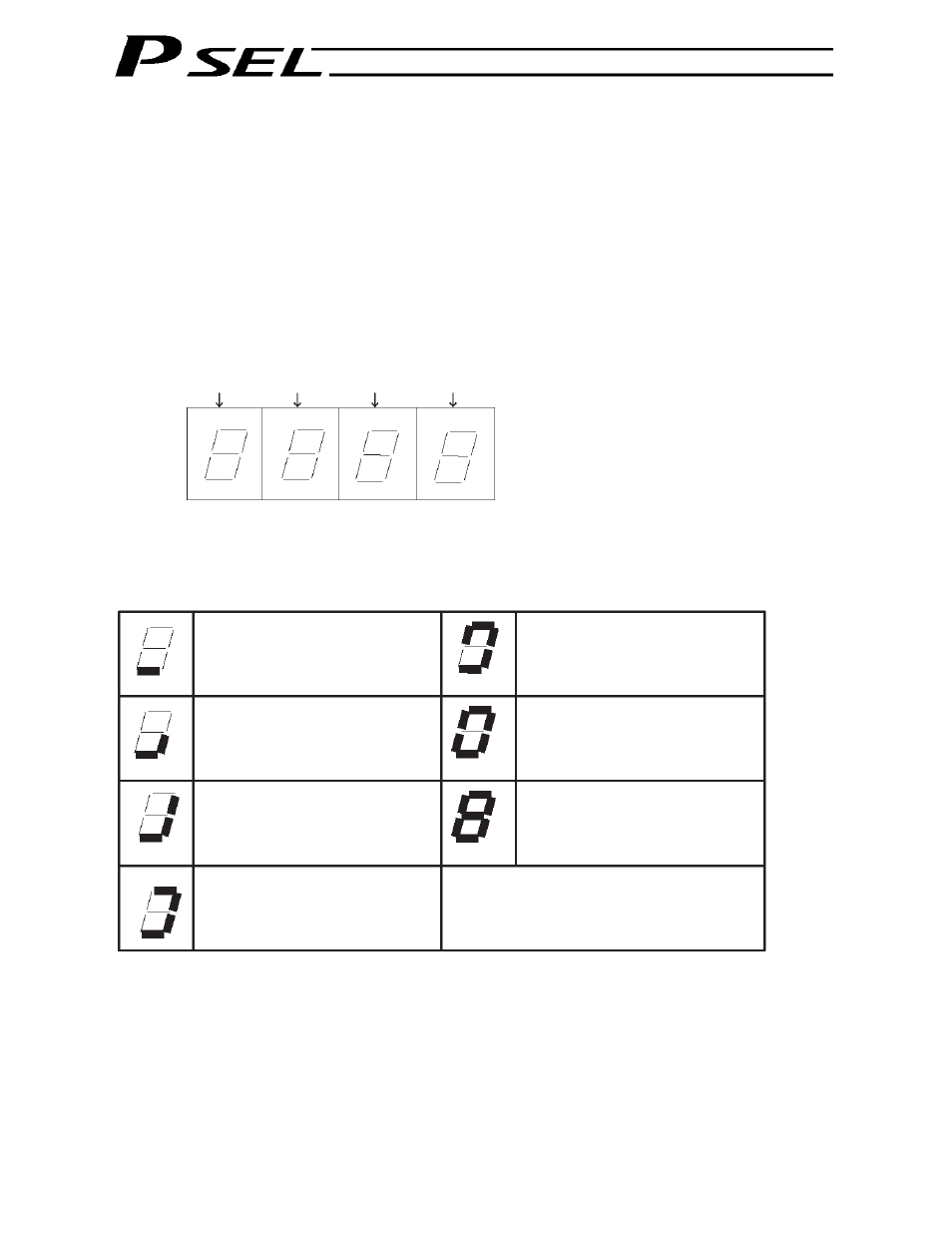
Example) If other parameter No. 49 is set to “1” and other parameter No. 50 to “1” for a 2-axis controller,
the far-right segment digit will show the current for axis 1.
Axis 2
Axis 1
When data is written to the flash ROM or a software reset (restart) is executed after the parameter values
have been input, the panel window will show the motor current to rating ratio (%) by a segment pattern,
instead of “ready status” or “program run number.”
The segment display patterns and corresponding motor current to rating ratios (%) are shown below.
Thick lines indicate illuminated segments.
0 < Motor current to rating ratio (%)
25
25 < Motor current to rating ratio (%)
50
50 < Motor current to rating ratio (%)
75
75 < Motor current to rating ratio (%)
100
100 < Motor current to rating ratio (%)
150
150 < Motor current to rating ratio (%)
200
200 < Motor current to rating ratio (%)