IAI America PSEL User Manual
Page 29
19
Part 1 Installation
[5] Axis 2 brake-release switch
(BK2):
This switch is used to forcibly release the electromagnetic brake of
the actuator constituting axis 2. The specifications are the same as
those of the axis 1 brake-release switch in [3].
[6] Axis 2 encoder/sensor
connector (PG2):
This connector is used to connect to the encoder cable for axis 2.
The specifications are the same as those of the axis 1
encoder/sensor connector in [4].
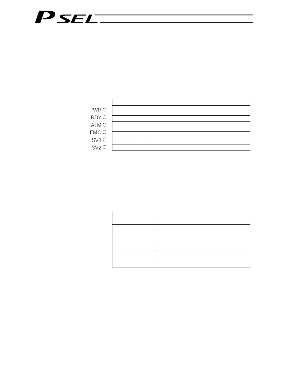
[7] LED indicators:
These indicators indicate the controller status.
Name
Color
Status when the LED is lit
PWR
Green
The controller has been started successfully and is
receiving power.
RDY
Green
The controller is ready.
ALM
Orange
An alarm is present (an error of message level or
higher has generated.)
EMG
Red An
emergency
stop is being actuated.
SV1
Green
The servo for axis 1 is on.
SV2
Green
The servo for axis 2 is on.
[8] Panel unit connector:
This connector is used to connect the optional panel unit.
[9] PIO connector:
This 34-pin, flat DIO connector consists of 24 inputs and eight
outputs.
Standard I/O Interface Specifications (key items)
Item Description
Connector name
I/O
Applicable connector
Flat connector, 34 pins
Power supply
Power is supplied from connector pin Nos. 1
and 34.
Inputs
24 points (including general-purpose inputs and
dedicated inputs)
Outputs
8 points (including general-purpose outputs and
dedicated outputs)
Connected to
External PLC, sensor, etc.