428 appen dix – IAI America PSEL User Manual
Page 438
428
Appen
dix
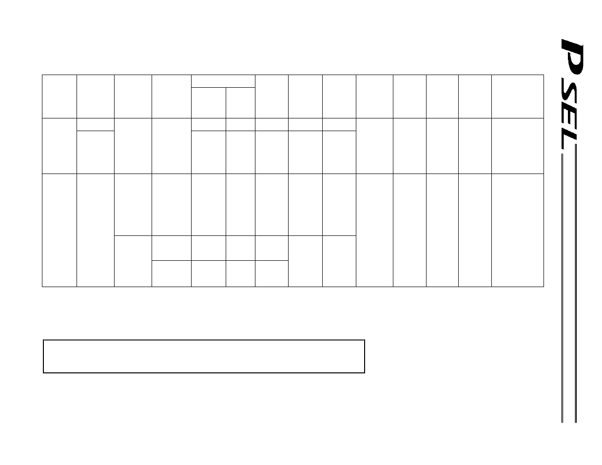
Combination Table of PSEL Linear/Rotary Control Parameters
Permitted encoder
processing method
Axis-specific
parameter
No. 1, Axis
operation
type
Axis-specific
parameter No.
68, Mode
selection for
linear
movement
axis
Axis-specific
parameter No.
66, Mode
selection for
rotational
movement
axis
Axis-specific
parameter No.
67, Short-cut
control
selection for
rotational
movement axis
Simplified
absolute unit
INC
Expression
of current
position
(approx.)
Axis-specific
parameter
No. 7, Soft
limit +
Axis-specific
parameter
No. 8, Soft
limit -
Axis-specific
parameter No.
44, Length
measurement
correction
Axis-specific
parameter
No. 47,
Screw lead
Axis-specific
parameter
No. 50,
Gear ratio
numerator
Axis-specific
parameter
No. 51, Gear
ratio
denominator
Input unit
0
(Normal mode)
Counter
range
Valid Valid
0
(Linear
movement
axis)
1
(Infinite stroke
mode)
* Duty-cycle
timeout check
must be
examined.
Invalid Invalid
X
-10000 ~
9999.99
(Rotary)
Invalid
(Note)
Invalid
(Note)
Valid Valid Valid Valid
Distance mm
Speed mm/sec
Acceleration/
deceleration
G
0
(Normal mode)
0
(Short-cut
control not
selected)
* Specification
of values
other than “0”
is prohibited
in the normal
mode.
Counter
range
Valid Valid
0
(Short-cut
control not
selected)
Counter
range
1
(Rotational
movement
axis)
Invalid
1
(Index mode)
1
(Short-cut
control
selected)
X
0 ~ 359.999
(Rotary)
Invalid
(Fixed to
“359.999”
internally.)
Invalid
(Fixed to “0”
internally.)
Invalid Invalid Valid Valid
Angle mm deg
Angular velocity
mm/sec
deg/sec
Angular
acceleration/decel
eration G = 9807
mm/sec2
9807
deg/sec2
= 9807 x 2
/ 360
rad/sec2
* Degree
values
indicate the
angles of the
rotating body at
the end.
(Note)
If a positioning command other than “J
W” is issued by specifying a value outside the coordinate range of approx. -9990 to 9990, an
error (CBE, “Target-locus boundary over error”) will occur.
If a positioning command other than “J
W” is issued outside the coordinate range of approx. -9990 to 9990, an error (CC5,
“Positioning boundary pull-out error”) will occur.
Note: On actuators using a simplified absolute unit, the following settings are disabled:
Set the infinite stroke mode (“1”) for a linear movement axis
Select the short-cut control (“1”) for a rotational movement axis in the index mode