Chapter 4 2-axis independent mode, Chapter 4, Axis independent mode – IAI America PSEL User Manual
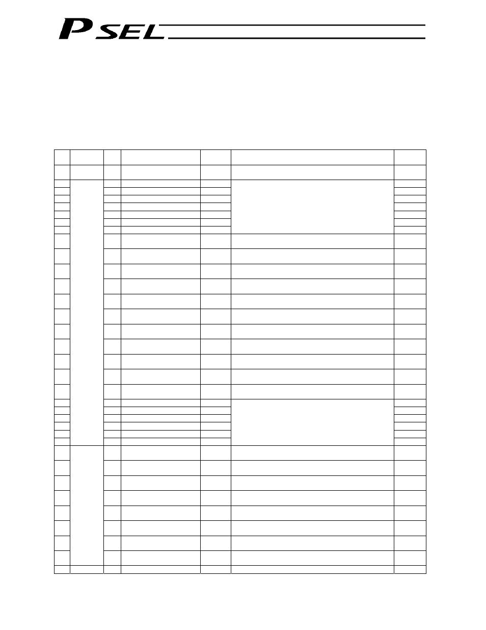
Page 334: I/o interface list
324
Part 3 Positioner Mode
Chapter 4 2-axis Independent Mode
With the 2-axis specification, each axis can be controlled separately in this mode. A set of signals, such as
the start input signal and positioning complete output signal, are provided for each axis.
Although the position number specification applies commonly to both axes, 13 bits of position inputs 1
through 13 (PC1 through 13) are divided into position-number specification bits for axis 1 and
position-number specification bits for axis 2.
1. I/O
Interface
List
Pin
No.
Category
Port
No.
Signal name
Signal
symbol
Function overview
Cable
color
1A P24
External power supply 24
V
P24
1-Brown
1B
016 Position input 7
PC7
1-Red
2A
017 Position input 8
PC8
1-Orange
2B
018 Position input 9
PC9
1-Yellow
3A
019 Position input 10
PC10
1-Green
3B
020 Position input 11
PC11
1-Blue
4A
021 Position input 12
PC12
1-Purple
4B
022 Position input 13
PC13
(Same as position inputs 1 through 6)
1-Gray
5A 023
Error
reset
RES
Present alarms will be reset at the leading edge of this
signal.
1-White
5B
000 Axis 1 start
CSTR1
Axis 1 will start moving at the leading edge of this
signal.
1-Black
6A
001 Axis 1 home return
HOME1
Axis 1 will start home-return operation at the leading
edge of this signal.
2-Brown
6B
002 Axis 1 servo ON
SON1
The servo for axis 1 will remain on while this signal is
ON, and remain off while this signal is OFF.
2-Red
7A
003 *Axis 1 pause
*STP1
Axis 1 can be moved when this signal turns ON, and will
decelerate to a stop when the signal turns OFF.
2-Orange
7B
004 *Axis 1 cancellation
*CANC
The remaining travel distance of axis 1 will be cancelled
if this signal turns OFF.
2-Yellow
8A
005 Axis 2 start
CSTR2
Axis 2 will start moving at the leading edge of this
signal.
2-Green
8B
006 Axis 2 home return
HOME2
Axis 2 will start home-return operation at the leading
edge of this signal.
2-Blue
9A
007 Axis 2 servo ON
SON2
The servo for axis 2 will remain on while this signal is
ON, and remain off while this signal is OFF.
2-Purple
9B
008 *Axis 2 pause
*STP2
Axis 2 can be moved when this signal turns ON, and will
decelerate to a stop when the signal turns OFF.
2-Gray
10A
009 *Axis 2 cancellation
*CANC2
The remaining travel distance of axis 2 will be cancelled
if this signal turns OFF.
2-White
10B
010 Position input 1
PC1
2-Black
11A
011 Position input 2
PC2
3-Brown
11B
012 Position input 3
PC3
3-Red
12A
013 Position input 4
PC4
3-Orange
12B
014 Position input 5
PC5
3-Yellow
13A
Input
015 Position input 6
PC6
Thirteen bits of position inputs 1 through 13 are divided
into position-number specification bits for axis 1 and
position-number specification bits for axis 2.
3-Green
13B 300
*Alarm
*ALM
This signal remains ON if the controller is normal. It will
turn OFF if an alarm occurs.
3-Blue
14A 301
Ready
RDY
This signal will turn ON when the controller becomes
ready.
3-Purple
14B 302
Axis 1 positioning
complete
PEND1
This signal will turn ON once axis 1 has moved to the
target position and entered the positioning band.
3-Gray
15A 303
Axis 1 home-return
complete
HEND1
This signal is OFF when the power to axis 1 is input,
and will turn ON when home return is completed.
3-White
15B
304 Axis 1 servo ON
SVON1
This signal will turn ON when the servo for axis 1 is
turned on, and turn OFF when the servo is turned off.
3-Black
16A 305
Axis 2 positioning
complete
PEND2
This signal will turn ON once axis 2 has moved to the
target position and entered the positioning band.
4-Brown
16B 306
Axis 2 home-return
complete
HEND2
This signal is OFF when the power to axis 2 is input,
and will turn ON when home return is completed.
4-Red
17A
Output
307 Axis 2 servo ON
SVON2
This signal will turn ON when the servo for axis 2 is
turned on, and turn OFF when the servo is turned off.
4-Orange
17B
N
External power supply 0 V
N
4-Yellow
*: Contact B (always ON)