Figure 3-13, P30 backplane connector pinout - rows a to d, Figure 3-14 – Artesyn ATCA-7470 Installation and Use (October 2014) User Manual
Page 79: P30 backplane connector pinout - rows e to h, Controls, indicators, and connectors
Controls, Indicators, and Connectors
ATCA-7470 Installation and Use (6806800P15K)
79
IPMI (IPMB1_xxx, ISMB_xxx)
Power (VP12_RTM, V3P3_RTM, VP5_RTM)
SAS Update channels
General control signals (BD_PRESENTx, RTM_PRSNT_N, RTM_RST_KEY-, RTM_RST-)
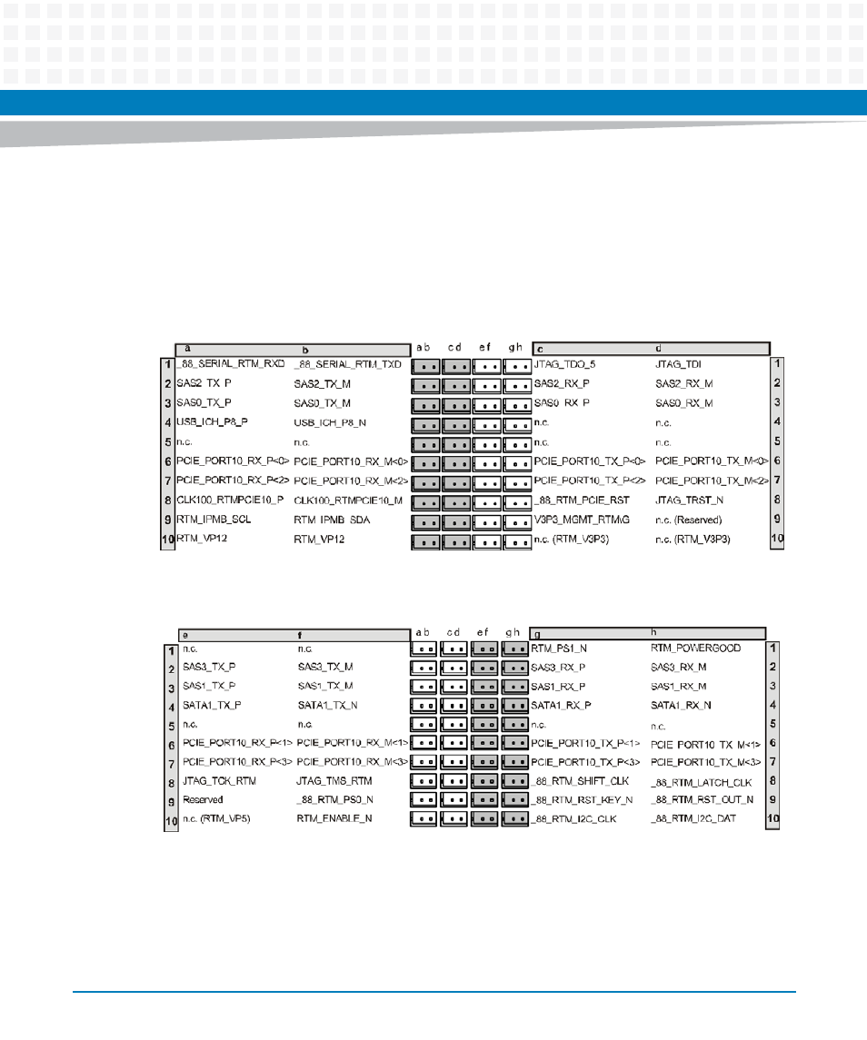
Figure 3-13 P30 Backplane Connector Pinout - Rows A to D
Figure 3-14 P30 Backplane Connector Pinout - Rows E to H