3 blade layout, Figure 2-2, Atca-7470 blade layout – Artesyn ATCA-7470 Installation and Use (October 2014) User Manual
Page 52: Figure "atca, Hardware preparation and installation
Hardware Preparation and Installation
ATCA-7470 Installation and Use (6806800P15K)
52
2.3
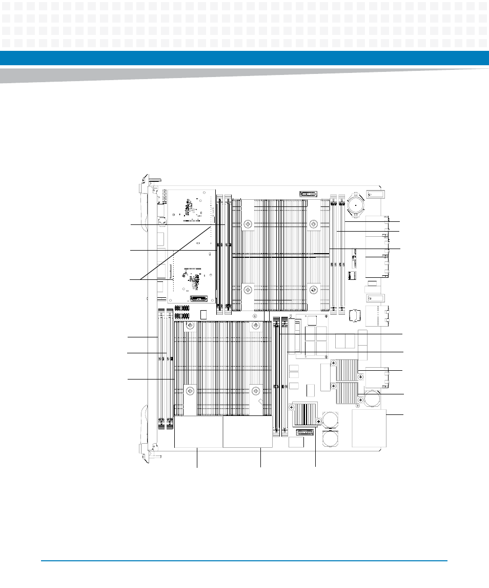
Blade Layout
The following figure shows the location of components on the ATCA-7470:
Figure 2-2
ATCA-7470 Blade Layout
J22 (DIMM6)
J21 (DIMM5)
ACC Module
Connectors
J14 (DIMM4)
J13 (DIMM3)
CPU 0
Intel PCH
ATCA PIM
DCDC
ZONE 1
FAB 1
FAB 2
J11 (DIMM1)
J12 (DIMM2)
CPU 1
J24 (DIMM8)
J23 (DIMM7)