24 base interface link status signals register, Table 6-52, Base interface link status signals register – Artesyn ATCA-7470 Installation and Use (October 2014) User Manual
Page 183: Maps and registers
Maps and Registers
ATCA-7470 Installation and Use (6806800P15K)
183
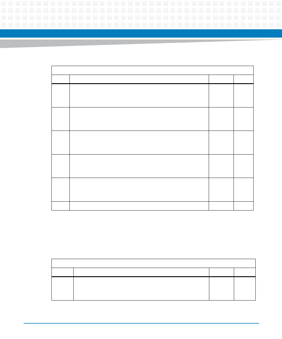
6.4.24 Base Interface link Status Signals Register
This register reflects the actual status of the external BASEIFx_LINKLOSS signals.
1
Represents the temperature status of CPU0 memory channel 2,3
0: Temperature threshold crossed
1: Normal working temperature
Ext.
r
2
Represents the temperature status of CPU1 memory channel 0,1
0: Temperature threshold crossed
1: Normal working temperature
Ext.
r
3
Represents the temperature status of CPU1 memory channel 2,3
0: Temperature threshold crossed
1: Normal working temperature
Ext.
r
4
Temperature status of the CPU0 memory voltage regulator
0: Temperature threshold crossed
1: Normal working temperature
Ext.
r
5
Temperature status of the CPU1 memory voltage regulator
0: Temperature threshold crossed
1: Normal working temperature
Ext.
r
7:6
Reserved
0
r
Table 6-51 Memory Temperature Status Register (continued)
Address Offset: 0x55
Bit
Description
Default
Access
Table 6-52 Base Interface Link Status Signals Register
Address Offset: 0x56
Bit
Description
Default
Access
0
Base interface 1 link status (Status of BASEIF1_LINKLOSS signal)
0:Link established
1:Link is down
Ext.
r