Aux interface, Video interface, Aux interface -12 – Altera DisplayPort MegaCore Function User Manual
Page 28: Video interface -12
AUX Interface
The IP core has three ports that control the serial data across the AUX channel:
• Data input (
tx_aux_in
)
• Data output (
tx_aux_out
)
• Output enable (
tx_aux_oe
). The output enable port controls the direction of data across the bidirec‐
tional link.
These ports are clocked by the source’s 16 MHz clock (
aux_clk
). The AUX channel’s physical layer is a
bidirectional 2.5 V SSTL Class II interface.
The source’s AUX controller allows you to capture all bytes sent from and received by the AUX channel,
which is useful for debugging. The IP core provides a standard stream interface that you can use to drive
an Avalon-ST FIFO component directly.
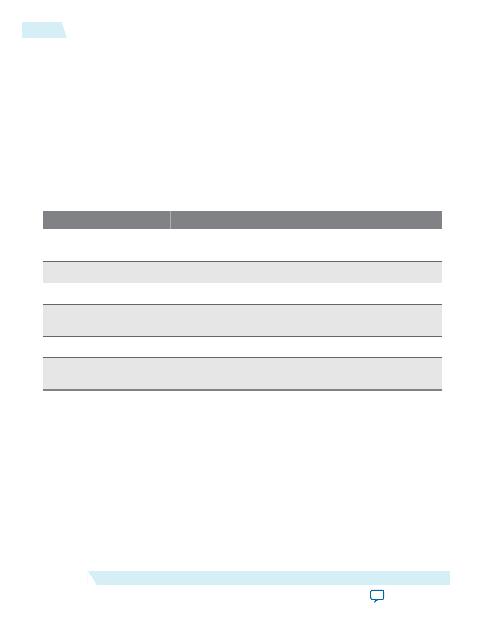
Table 4-9: Source AUX Debug Interface Ports
Port
Comments
tx_aux_debug_data[31:0]
The source AUX debug interface inserts a 1 µs timestamp counter in bits
[31:8]; bits [7:0] represent the byte received or transmitted.
tx_aux_debug_valid
Qualifies valid stream data.
tx_aux_debug_sop
Indicates the message packet’s first byte.
tx_aux_debug_eop
Indicates the message packet’s last byte. The last byte should be ignored
and is not part of the message.
tx_aux_debug_err
Indicates if the IP core detects an error in the current byte.
tx_aux_debug_cha
Indicates the direction of the current byte. 1 = byte transmitted by the
source, 0 = byte received from the sink.
Related Information
Video Interface
The core sends video to be encoded through the
txN_video_in
interface, which provides a standard H-
sync and V-sync input with support for interlaced or progressive video. You specify the data input width
via a parameter. The same input port transfers RGB and YCbCr data in either 4:4:4 or 4:2:2 color format.
Data is most-significant bit aligned and formatted for 4:4:4.
4-12
AUX Interface
UG-01131
2015.05.04
Altera Corporation
DisplayPort Source