Altera DisplayPort MegaCore Function User Manual
Page 101
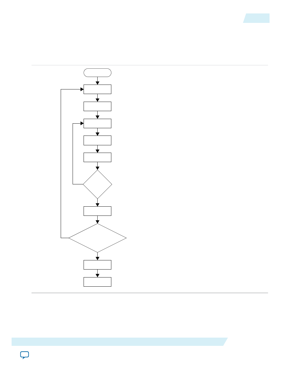
Figure 7-8: RX, TX and TX Analog Reconfiguration Manager FSM for Arria 10 Devices
This flow chart shows the reconfiguration flow for the RX, TX, and TX Analog . The FSM flow is similar
for RX, TX, and TX Analog. The FSM happens in sequence and it is controlled by the Reconfiguration
Top Manager. The Arria 10 reconfiguration uses read-modified-write operation to ensure only affected
configuration register bits are updated.
INIT
IDLE
INIT_WR
RD
MOD
WR
TRANS
If Last Offset
yes
no
END_INIT_WR
If Last Channel
yes
no
RESET
DONE
END INIT
The INIT state loads 0x02 to data and 0x00 to address for each channel.
The INIT_WR state initiates the Avalon-MM write cycle. Writing 0x02
to address 0x00 takes over the transceiver microcontroller.
The RD state reads the respective offset data from the transceiver.
The MOD state loads the read data and the data to be updated,
reconfigured, or modified into the data array. The WR state initiates
the Avalon-MM write cycle to the respective offset.
The TRANS state checks whether this offset is the last one that needs
to be modified or updated. If no, go back to the RD, MOD, WR
operation. If yes, move to the next channel or the operation is done.
Before moving to the next channel or DONE, the END_INIT state
loads 0x03 to data and 0x00 to address for each channel.
END_INIT_WR initiates the Avalon-MM write operation to hand
over the microcontroller ownership. The END_INIT_WR state also
checks whether another channel needs to be updated. If yes, the
operation moves to the INIT state to start the operation for the next
channel.
After all channels are reconfigured, the RESET state initiates the reset
to the transceiver reset module to complete the entire operation. When
the reset module is ready, the operation moves to DONE and IDLE.
UG-01131
2015.05.04
Arria 10 Finite-State Machine (FSM)
7-13
DisplayPort IP Core Simulation Example
Altera Corporation