Altera DDR SDRAM High-Performance Controllers and ALTMEMPHY IP User Manual
Page 79
Chapter 5: Functional Description—ALTMEMPHY
5–33
ALTMEMPHY Signals
June 2011
Altera Corporation
External Memory Interface Handbook Volume 3
Section I. DDR and DDR2 SDRAM Controllers with ALTMEMPHY IP User Guide
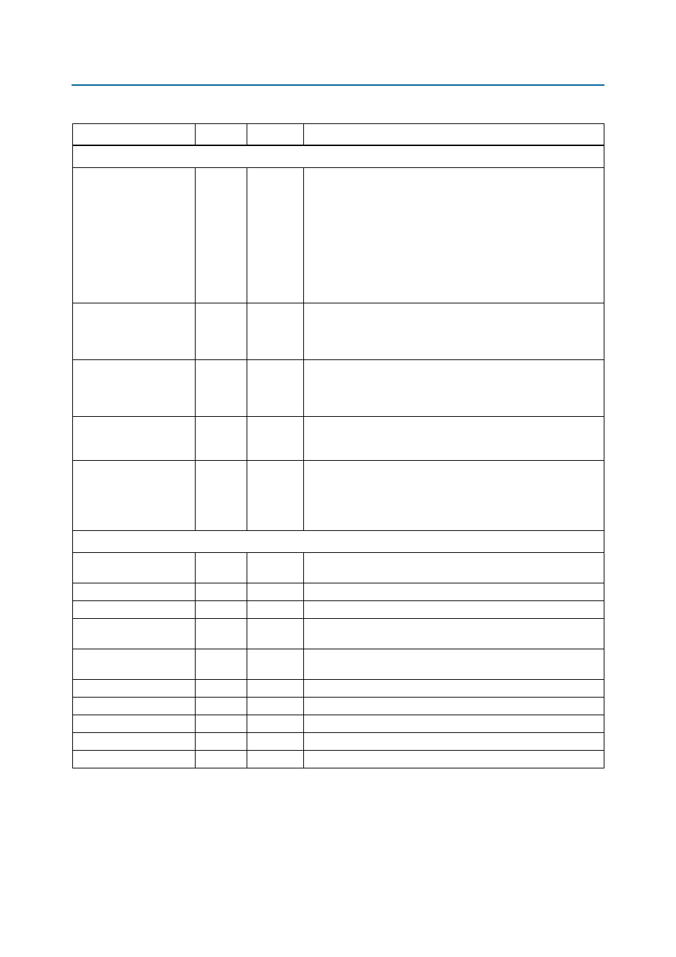
Calibration Interface Signals—without leveling only
rsu_codvw_phase
Output
—
The sequencer sweeps the phase of a resynchronization clock across
360° or 720° of a memory clock cycle. Data reads from the DIMM
are performed for each phase position, and a data valid window is
located, which is the set of resynchronization clock phase positions
where data is successfully read. The final resynchronization clock
phase is set at the center of this range: the center of the data valid
window or CODVW. This output is set to the current calculated value
for the CODVW, and represents how many phase steps were
performed by the PLL to offset the resynchronization clock from the
memory clock.
rsu_codvw_size
Output
—
The final centre of data valid window size (rsu_codvw_size) is the
number of phases where data was successfully read in the
calculation of the resynchronization clock centre of data valid
window phase (rsu_codvw_phase).
rsu_read_latency
Output
—
The rsu_read_latency output is then set to the read latency (in
phy_clk
cycles) using the rsu_codvw_phase resynchronization
clock phase. If calibration is unsuccessful then this signal is
undefined.
rsu_no_dvw_err
Output
—
If the sequencer sweeps the resynchronization clock across every
phase and does not see any valid data at any phase position, then
calibration fails and this output is set to 1.
rsu_grt_one_dvw_
err
Output
—
If the sequencer sweeps the resynchronization clock across every
phase and sees multiple data valid windows, this is indicative of
unexpected read data (random bit errors) or an incorrectly
configured PLL that must be resolved. Calibration has failed and this
output is set to 1.
Unused Signals
hc_scan_enable_
access
Input
—
This signal is unused; you should connect this signal to logic level 0.
hc_scan_enable_dq
Input
—
This signal is unused; you should connect this signal to logic level 0.
hc_scan_enable_dm
Input
—
This signal is unused; you should connect this signal to logic level 0.
hc_scan_enable_
dqs
Input
—
This signal is unused; you should connect this signal to logic level 0.
hc_scan_enable_
dqs_config
Input
—
This signal is unused; you should connect this signal to logic level 0.
hc_scan_din
Input
—
This signal is unused; you should connect this signal to logic level 0.
hc_scan_update
Input
—
This signal is unused; you should connect this signal to logic level 0.
hc_scan_ck
Input
—
This signal is unused; you should connect this signal to logic level 0.
hc_scan_dout
Output
—
This signal is unused; you should connect this signal to logic level 0.
mem_err_out_n
Input
—
This signal is unused; you should connect this signal to logic level 1.
Notes to
Table 5–7
:
(1) The debug interface uses the simple Avalon-MM interface protocol.
(2) These ports exist in the Quartus II software, even though the debug interface is for Altera’s use only.
Table 5–7. Other Interface Signals (Part 3 of 3)
Signal Name
Type
Width
Description