Altera DDR SDRAM High-Performance Controllers and ALTMEMPHY IP User Manual
Page 78
5–32
Chapter 5: Functional Description—ALTMEMPHY
ALTMEMPHY Signals
External Memory Interface Handbook Volume 3
June 2011
Altera Corporation
Section I. DDR and DDR2 SDRAM Controllers with ALTMEMPHY IP User Guide
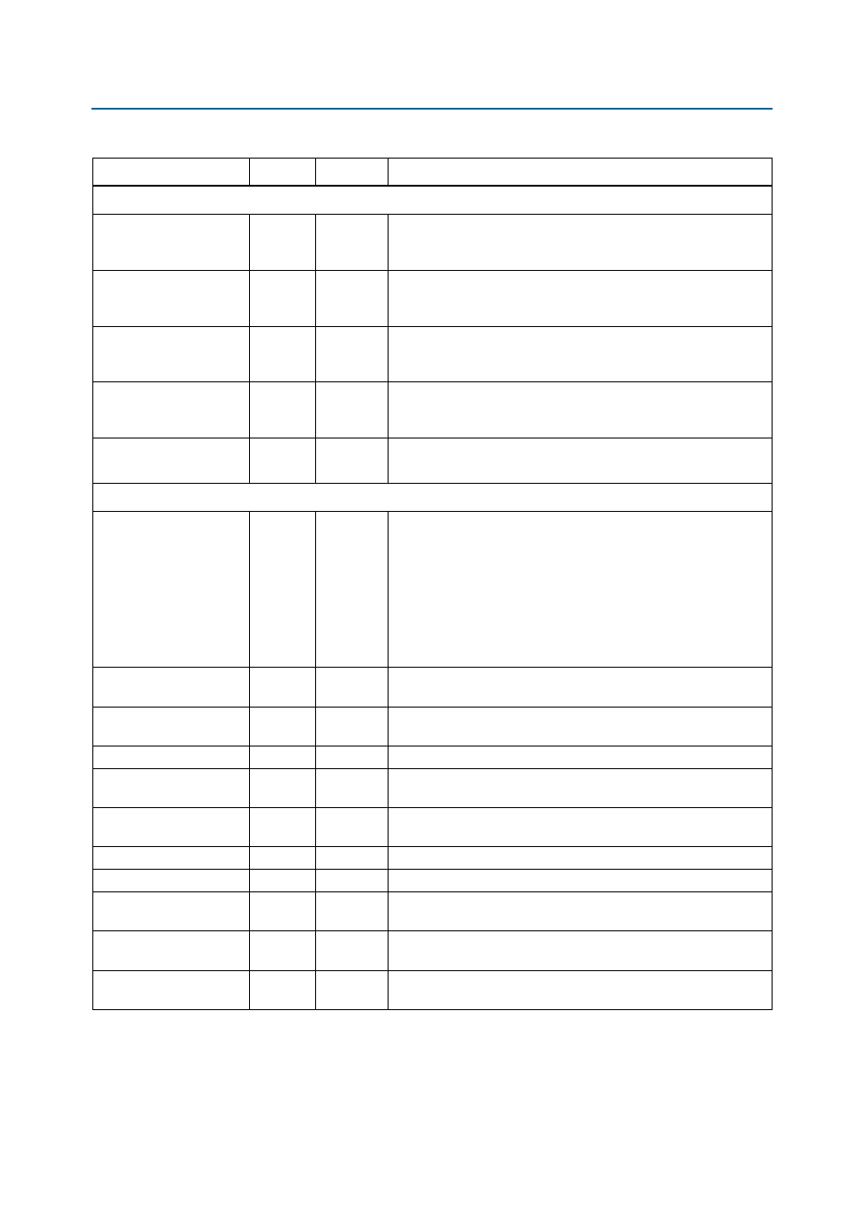
PLL Reconfiguration Signals—Stratix III and Stratix IV Devices
pll_reconfig_enable
Input
1
This signal enables the PLL reconfiguration I/O, and is used if the
user requires some custom PLL phase reconfiguration. It should
otherwise be tied low.
pll_phasecountersele
ct
Input
4
When pll_reconfig_enable is asserted, this input is directly
connected to the PLL's phasecounterselect input. Otherwise this
input has no effect.
pll_phaseupdown
Input
1
When pll_reconfig_enable is asserted, this input is directly
connected to the PLL's phaseupdown input. Otherwise this input has
no effect.
pll_phasestep
Input
1
When pll_reconfig_enable is asserted, this input is directly
connected to the PLL's phasestep input. Otherwise this input has
no effect.
pll_phase_done
Output
1
Directly connected to the PLL's phase_done output.
PLL Reconfiguration Signals—Stratix II Devices
pll_reconfig_
enable
Input
1
Allows access to the PLL reconfiguration block. This signal should
be held low in normal operation. While the PHY is held in reset (with
soft_reset_n
), and reset_request_n is 1, it is safe to
reconfigure the PLL. To reconfigure the PLL, set this signal to 1 and
use the other pll_reconfig signals to access the PLL. When
finished reconfiguring set this signal to 0, and then set the
soft_reset_n
signal to 1 to bring the PHY out of reset. For this
signal to work, the PLL_RECONFIG_PORTS_EN GUI parameter must
be set to TRUE.
pll_reconfig_
write_param
Input
9
Refer to
, for more information.
pll_reconfig_read_pa
ram
Input
9
Refer to
, for more information.
pll_reconfig
Input
1
Refer to
, for more information.
pll_reconfig_
counter_type
Input
4
Refer to
, for more information.
pll_reconfig_
counter_param
Input
3
Refer to
, for more information.
pll_reconfig_data_in
Input
9
Refer to
for more information.
pll_reconfig_busy
Output
1
Refer to
, for more information.
pll_reconfig_data_ou
t
Output
9
Refer to
, for more information.
pll_reconfig_clk
Output
1
Synchronous clock to use for any logic accessing the
pll_reconfig
interface. The same as aux_scan_clk.
pll_reconfig_
reset
Output
1
Resynchronised reset to use for any logic accessing the
pll_reconfig
interface.
Table 5–7. Other Interface Signals (Part 2 of 3)
Signal Name
Type
Width
Description