Memory settings, Memory settings –2 – Altera DDR SDRAM High-Performance Controllers and ALTMEMPHY IP User Manual
Page 28
3–2
Chapter 3: Parameter Settings
ALTMEMPHY Parameter Settings
External Memory Interface Handbook Volume 3
June 2011
Altera Corporation
Section I. DDR and DDR2 SDRAM Controllers with ALTMEMPHY IP User Guide
The following sections describe the four tabs of the Parameter Settings page in more
detail.
Memory Settings
In the Memory Settings tab, you can select a particular memory device for your
system and choose the frequency of operation for the device. Under General Settings,
you can choose the device family, speed grade, and clock information. In the middle
of the page (left-side), you can filter the available memory device listed on the right
side of the Memory Presets dialog box, refer to
Figure 3–1
. If you cannot find the
exact device that you are using, choose a device that has the closest specifications,
then manually modify the parameters to match your actual device by clicking Modify
parameters
, next to the Selected memory preset field.
Table 3–1
describes the General Settings available on the Memory Settings page of
the ALTMEMPHY parameter editor.
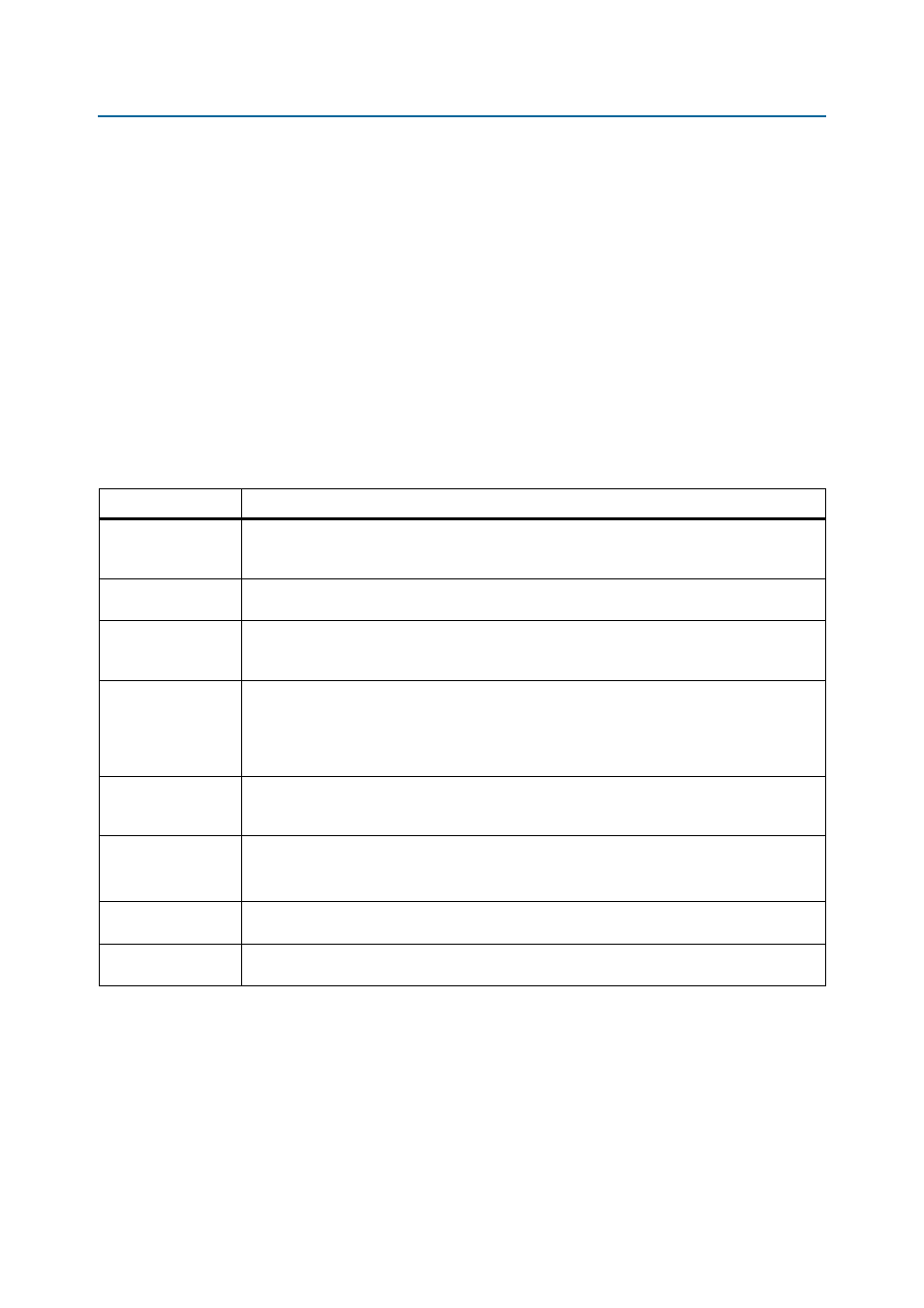
Table 3–1. General Settings
Parameter Name
Description
Device family
Targets device family (for example, Stratix III).
shows supported device
families. The device family selected here must match the device family selected on the MegaWizard
page 2a.
Speed grade
Selects a particular speed grade of the device (for example, 2, 3, or 4 for the Stratix III device
family).
PLL reference clock
frequency
Determines the clock frequency of the external input clock to the PLL. Ensure that you use three
decimal points if the frequency is not a round number (for example, 166.667 MHz or 100 MHz) to
avoid a functional simulation or a PLL locking problem.
Memory clock
frequency
Determines the memory interface clock frequency. If you are operating a memory device below its
maximum achievable frequency, ensure that you enter the actual frequency of operation rather than
the maximum frequency achievable by the memory device. Also, ensure that you use three decimal
points if the frequency is not a round number (for example, 333.333 MHz or 400 MHz) to avoid a
functional simulation or a PLL locking issue.
Controller data rate
Selects the data rate for the memory controller. Sets the frequency of the controller to equal to
either the memory interface frequency (full-rate) or half of the memory interface frequency
(half-rate).
Enable half rate bridge
This option is only available for HPC II.
Turn on to keep the controller in the memory full clock domain while allowing the local side to run
at half the memory clock speed, so that latency can be reduced.
Local interface clock
frequency
Value that depends on the memory clock frequency and controller data rate, and whether or not
you turn on the Enable Half Rate Bridge option.
Local interface width
Value that depends on the memory clock frequency and controller data rate, and whether or not
you turn on the Enable Half Rate Bridge option.